

Abstract
Microfluidics is a flourishing field, enabling a wide range of biochemical and clinical applications such as cancer screening, micro-physiological system engineering, high-throughput drug testing, and point-of-care diagnostics. However, fabrication of microfluidic devices is often complicated, time consuming, and requires expensive equipment and sophisticated cleanroom facilities. Three-dimensional (3D) printing presents a promising alternative to traditional techniques such as lithography and PDMS-glass bonding, not only by enabling rapid design iterations in the development stage, but also by reducing the costs associated with institutional infrastructure, equipment installation, maintenance, and physical space. With the recent advancements in 3D printing technologies, highly complex microfluidic devices can be fabricated via single-step, rapid, and cost-effective protocols, making microfluidics more accessible to users. In this review, we discuss a broad range of approaches for the application of 3D printing technology to fabrication of micro-scale lab-on-a-chip devices.
Export citation and abstract BibTeX RIS
1. Introduction
Three-dimensional (3D) printing is a fabrication process which enables translation of 3D computer designs into physical models through the additive patterning of a material using a print head, nozzle, or other mechanisms [1–3]. The history of printing, which ultimately gave rise to 3D printing, starts with woodblock printing around the year 200 in China. A pattern was carved into a block of wood, which was then used to repeatedly form an imprint on a substrate. Since the invention of this approach, printing has evolved through the printing press, movable type, lithography, xerography, and laser printing to 3D printing (figure 1). Additive manufacturing approaches include fused deposition modeling (FDM) and stereolithography (SLA) which involve conversion of a digital 3D design to 2D slices for layer-by-layer construction [1]. FDM involves melting a thermoplastic polymer using a heated nozzle and depositing layers which solidify and form a 3D structure. SLA employs a beam of light to polymerize layers of a liquid photo-curable resin. Hybrid printers, such as multi-jet modeling printers, combine FDM and SLA methods by extruding a photo-curable resin and polymerizing it using light [2]. 3D printing has revolutionized the prototyping workflow over the past decade [4–6].

Figure 1. Timeline of printing technology. Woodblock printing was the earliest printing technique, dating circa 200 [74]. The first printed book dates circa 868 [75]. The development of printing technology results in movable type [76] and the printing press including Johannes Gutenberg's printing press [77], the stone lithography press [78], the stanhope press [79], Koenig's steam printing press [80], and the rotatory printing press [81]. In 1935, the invention of xerography revolutionized printing technology. In 1983, the first 3D printer [82] was introduced by Chuck Hall, followed by desktop 3D printers [83]. Images are reproduced with permission6.
Download figure:
Standard image High-resolution imageA microfluidic device is a set of micro-scale channels designed and fabricated for handling small quantities of reagents for numerous chemical and biological applications. These devices have been designed to carry out disease diagnostics in point-of-care settings, culture cells with a precisely controllable microenvironment, and examine chemical and biological processes with a high level of precision [7–10]. Using microfluidic devices reduces the consumption of reagents and biological samples, increases throughput, and lowers the fabrication and operation cost. Microfluidic devices may be categorized into passive and active components. Active microfluidic components, such as pumps and valves, require energy to manipulate the fluid flow where the passive microfluidic components, such as channels, mixers and separators, rely on external actuation or capillary forces to regulate fluid flow. In an interesting approach, microfluidic devices can be made by assembling simple microfluidic modules which have been fabricated separately to create a variety of devices suited for particular applications. The modular microfluidic approach gives versatility to the fabrication of complex microfluidic devices. Traditional approaches to fabricate microfluidic devices tend to be complex and time-consuming, generally involving cleanroom microfabrication of a master from a 2D photomask followed by soft lithography and bonding. This ubiquitous protocol, however, introduces significant costs associated with institutional infrastructure, equipment installation, maintenance, and physical space required for cleanroom facilities. This limits accessibility to microfluidic technologies for many research labs. Further, every design iteration requires printing of a new photomask and UV lithography to produce a new master [11, 12]. This multi-step, labor-intensive process currently hinders rapid and widespread innovation and the development of new applications [13].
In the past decade, a wave of technological advancements in high-resolution 3D printing has further enhanced our ability to fabricate micro-scale structures and microfluidic devices [12, 14–16]. Using this technology, microfluidic devices can be printed in single step. In a different approach, 3D printers are used to create a master mold that may be used for soft lithography using PDMS. In both approaches, use of 3D printing technology replaces the cleanroom microfabrication steps, easing the fabrication of complex devices and reducing the startup investment and operational costs compared to the traditional fabrication [8, 11, 13]. Using this technology, alteration of the design features is significantly easier than traditional fabrication, enabling agile iterative design and facilitating rapid prototyping. In this way, 3D printing can make microfluidic technology more accessible to researchers in various fields and accelerates innovation in the field of microfluidics [17]. For example, SLA technology has been shown to offer high quality feature reproduction and optical transparency comparable to other rapid prototyping approaches including soft lithography and infrared laser micromachining [18]. Previous related reviews [1, 16, 17, 19–21] mainly discuss the 3D printing technologies used for fabrication of microfluidics and applications of 3D-printed microfluidics. Here, in a different approach, we present several 3D-printed microfluidic fabrication techniques (e.g. 3D printed mold fabrication) and their wide range of useful applications, including practical insights about how existing technologies and materials have been used previously and may be applied in the future. We describe several passive and active components which achieve precise control over fluid flow, modular assembly of such components, as well as complete 3D-printed microfluidic devices. The 3D-printed mold approach is also presented as an intermediate phase to take advantage of the rapid prototyping capabilities of 3D printing as well as the advantages of traditional PDMS-glass microfluidic devices. 3D-printable materials are also presented as an important consideration unique to the 3D printing approach as well as a direction for future innovation.
2. 3D printing technologies
2.1. Stereolithography (SLA)
SLA was first introduced by Chuck Hull [22] and became the first commercialized 3D printing technology. SLA 3D printers use UV light to cure liquid polymers in a layer-by-layer manner, building 3D structures on a build platform (figure 2(a)). UV light is generated and patterned using a UV laser source and a scanning mirror to raster pattern a design or, alternatively, a UV source and a digital micromirror device (DMD) to expose a 2D pattern within a layer of photo-curable resin [21, 23–25]. Either free surface or constrained surface approaches are used [21, 26]. In the free surface approach, a mobile build platform is submerged in a tank of photoactive liquid polymer and a laser beam or DMD system cures the polymer at the surface. In contrast, the constrained surface approach uses a mobile build platform suspended above the resin tank and the UV source, located under the tank, cures the pattern through the transparent bottom of the tank. Several groups have reported success with using SLA 3D printing for microfluidic device fabrication [27–29].

Figure 2. 3D printing technologies. (a) Stereolithography (SLA). (b) Fused deposition modeling (FDM). (c) Material jetting. (d) Photopolymer jetting. (e) Binder jetting. (f) Laser sintering. (g) Laser melting. (h) Electron beam melting. Reproduced with permission [84].
Download figure:
Standard image High-resolution image2.2. Fused Deposition Modeling (FDM)
FDM was first introduced by Scott Crump [30] and is now one of the most widely used rapid prototyping technologies [1]. FDM 3D printers work by melting and extruding a thermoplastic filament through a nozzle (figure 2(b)). To build a 3D structure, the melted material is deposited on the build platform then cools down and solidifies; this is repeated in a layer-by-layer fashion [21, 31, 32]. FDM works with inexpensive biocompatible polymers such as acrylonitrile butadiene styrene (ABS) and poly(lactic acid), which are known for their durability [16]. This prototyping method has been investigated in [12, 33, 34] for fabrication of microfluidic devices.
2.3. Material jetting
Material jetting 3D printers use inkjet print heads to jet melted wax-like materials (either model material or support) onto a mobile build platform. The material then cools and forms a solid 3D structure as this process is repeated layer-by-layer (figure 2(c)). This technology has generally been used for printing polymers, ceramics, metals and biomaterials [35].
2.4. Photopolymer jetting
Photopolymer jetting was originally introduced by Hanan Gothait [36]. It has recently been commercialized and made available in the consumer market. This approach uses the concept of inkjet printing to deposit model or support liquid photopolymers pointwise onto a mobile build platform. The materials are then cured by UV light and solidified, allowing layer-by-layer fabrication (figure 2(d)). This approach has been used in [37–41] to fabricate microfluidic devices.
2.5. Binder jetting
Binder jetting 3D printing is a technique similar to material and photopolymer jetting but the inkjet print heads apply a liquid adhesive onto thin layers of powder distributed on a build platform (figure 2(e)). This process binds the particles together to produce a solid structure and, when repeated, a 3D structure is built up layer-by-layer in the powder bed. This 3D printing approach does not need any support structures and works with almost any material that is available in powder form.
2.6. Laser sintering
Laser sintering 3D printers use a laser source and scanning mirrors to melt and coat a layer of plastic powder onto a build platform (figure 2(f)). Following the sintering of one layer, the build platform is lowered and the next layer of plastic powder is laid on top of the previous layer. By repeating this process, layers of the 3D structure are built up in the powder bed. Like binder jetting, this process does not require any support structures.
2.7. Laser melting
The working principal of laser melting 3D printing is similar to laser sintering in that a laser draws a raster pattern on a layer of powder to solidify a desired pattern. In contrast, laser melting printers build 3D structures from a metal powder. Further, these printers require support structures to anchor the part to the build platform (figure 2(g)) and to allow heat transfer away from the print to reduce thermal stress.
2.8. Electron beam melting
The concept of electron beam melting is similar to laser melting but in the place of a laser, an electron beam melts the metal powder (figure 2(h)). Electron beam melting generates lower thermal stress in the structure than laser melting which reduces the amount of support structures needed and increases the fabrication speed.
2.9. Hybrid processes
In hybrid 3D printing processes, designs are fabricated using a combination of the additive manufacturing methods described here with traditional manufacturing methods. The two steps of the fabrication occur in succession in a single machine.
3. 3D-printed microfluidic fabrication techniques
Affordable 3D printers have been used for fabrication of templates, or 'masters', for producing classical PDMS devices [42]. Components of microfluidic devices have been printed in a single step and assembled to produce functional devices. 3D printing has also been used for various unibody microfluidic devices, eliminating the need for post-processing steps.
3.1. Fabrication of molds for PDMS-based microfluidics
Fabricating PDMS-based microfluidics using 3D-printed master molds provides many of the advantages of 3D printing fabrication and maintains the desirable PDMS material properties such as biocompatibility and oxygen permeability. This approach also overcomes the disadvantage of unknown surface properties of commercial resins [43]. The master may be produced via rapid prototyping techniques, reducing the overall cost and time required for fabrication, followed by traditional PDMS molding. The convenience of these fabricated PDMS templates can be seen in that they do not require a cleanroom. Using this approach, microfluidic devices with structures of 10 μm have been generated at a low average cost (reported by one study to be approximately 0.48$US per chip) [42].
Comina et al fabricated masters for PDMS devices through micro-SLA [42]. During fabrication, the 3D-printed templates were rinsed in ethanol and airbrushed with a PDMS-compatible ink to protect the template surface and also allow the PDMS to cure completely. These coated templates were then used as masters for soft lithography with PDMS (figure 3(a)). Functionality was successfully demonstrated for glucose sensing techniques. Comina et al continued their investigation by fabricating a 3D-printed chip that could integrate many different functionalized bodies including PDMS films [44]. Here, 3D-printed monolithic, or unibody, lab-on-a-chip devices were fabricated using a high-resolution SLA 3D printer and characterized for their versatility and functionality, including passive and active transport, lateral flow, and micro-mixing. These chips show potential to serve as a universal platform, offering the ability to incorporate PDMS films with integrated substrates which may be prepared separately from this process. In this case, the unibody lab-on-a-chip device functionality was demonstrated through its ability to detect H2O2 concentration in blood. This method has several advantages including the printed chip's compatibility to various detection methods in addition to the low cost per device.

Figure 3. 3D-printed mold for PDMS microfluidic devices. (a) PDMS microfluidic mixer made using a 3D-printed mold; (1) 3D design of the mold for diffusion and chaotic mixers; (2) image of the cured PDMS on the 3D-printed mold; (3) 100 μm deep diffusion and (4) chaotic mixer showing the mixture of 1 mM fluorescein with 1 mM rhodamine B at 60 μl min−1. Reproduced with permission [42]. (b) Basket-woven PDMS crossover feature fabricated using a 3D-printed mold; (1) schematic of the fabrication process for crossover features; (2) image of PDMS crossover features loaded with yellow and blue dye solutions. The two streams are independent with no leakage into each other. Reproduced with permission [11]. (c) PDMS channels made using a 3D-printed mold; (1) design of the microfluidic channels with different heights (50, 100, 200, 500, 1000 and 2000 μm); (2) image of the 3D-printed mold; (3) image of the PDMS microfluidic device. Reproduced with permission [45].
Download figure:
Standard image High-resolution imageChan et al have developed 3D-printed masters used to fabricate 3D microfluidic PDMS networks in a one-step procedure [11]. The procedure to form 3D interconnected networks consists of fabricating a master with crossovers in a parallel, basket-weaving arrangement, followed by soft lithography (figure 3(b)). To achieve truly 3D microfluidic networks, including crossover features, the PDMS was partially cured then peeled from the master, creating a crack. This crack was then self-closed due to elasticity and self-adhesion of PDMS, then permanently cured by further thermal curing. To circumvent the issue of PDMS not curing fully at the surface of the 3D-printed master (presumably due to the residual monomers and catalyst on the master), the masters were heated, plasma treated, and coated with fluorinated silane prior to soft lithography. Functional microfluidic chips, including a 3D chaotic advective mixer and a peristalic valve, have been fabricated through this single-step technique.
Use of 3D-printed molds for PDMS devices is particularly promising for cell culture applications. Kamei et al investigated the use of a 3D-printed soft lithography mold for examining concentration gradients for biomedical applications [45]. The mold was fabricated by an ink-jet 3D printer and cured using UV light and PDMS was poured into the mold to create a 5 mm thick lab-on-a-chip device. This device was then used to examine the effect of concentration gradients of growth factors and the effect of embryonic stem cell survival and growth (figure 3(c)). Gross et al reported the design and fabrication of 3D-printed microfluidic electrical cell lysis devices that has been coated with PDMS or polystyrene to improve the cellular adherence for cell lysis [43].
Gelber et al took a different approach in mold fabrication by developing a sacrificial mold to create patterns, then proceeding to dissolve this structure to leave channels [34]. The procedure began with the creation of the sacrificial mold from isomalt (water soluble) cooled to a temperature below 55 °C, or its glass transition temperature, creating a stiff, clear glassy structure. Epoxy resin was poured over the pattern and the isomalt channels were dissolved with water. This process has many advantages over the traditional mold creation including the ability to create channels with round cross-sections which are more efficient in analyzing cells or other biomarkers. Additionally, this process can simplify devices and create channels with a large resistance per unit length. However, its fallback is the effect of the mold material on cells once dissolved due to the presence of sugar alcohols.
3.2. Microfluidic component fabrication
Fabrication of microfluidic devices with precise, micro-scale channel geometries generally requires a significant amount of labor in terms of design, fabrication and integration of microfluidic components [15], including active and passive components. Active components manipulate fluid flow by applying energy where passive components rely on external actuation or capillary forces to drive fluid flow. Further, microfluidic modules may be fabricated separately and later combined to achieve interchangeable design easily tailored to carry out a desired function.
3.2.1. Passive microfluidic components:
In recent years, substantial research has been carried out on 3D-printed passive microfluidic components. As a notable example, Shallan et al performed a study with the objective of cost-effective one-step fabrication of microfluidic components [2]. For this purpose, the authors utilized a digital micromirror-based SLA 3D printer. The low-viscosity resin used here was a combination of a modified acrylate oligomer and monomer, an epoxy monomer, a photoinitiator, and additives and was optically transparent with a transmittance of 60% at 430 nm. To demonstrate the application of the proposed 3D printer for fabricating complex microfluidic systems, a tap water nitrate analysis (Griess Test) component was developed, combining three fluidic layers and several passive components, including a micromixer (figure 4(a)(1)), a gradient generator (figure 4(a)(2)), a droplet generator, and a module for isotachophoresis. More recently, Donvito et al reported a T-junction droplet generator microfluidic device fabricated using a 3D printer (figure 4(b)). This approach has been shown to produce monodisperse droplets at a rate comparable to the conventional T-junctions reported in the literature [46].
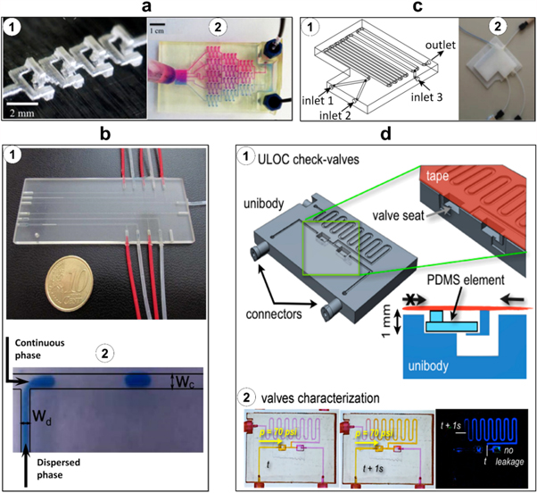
Figure 4. Passive 3D-printed microfluidic components. (a) 3D-printed micromixer and gradient generator; (1) four mixing units printed horizontally; (2) gradient generation tested with two colored dyes, rhodamine B (top) and bromothymol blue (bottom). Reproduced with permission [2]. (b) 3D-printed T-junction droplet generator; (1) droplet generator microfluidic device (with dimensions of 3 cm by 8 cm by 0.5 cm) containing six independent and identical rectangular T-junctions; (2) image of a droplet generated in the T-junction. The width of the dispersed phase flow channel (Wd) and continuous phase flow channel (Wc) are 200 μm and 400 μm, respectively. Reproduced with permission [46]. (c) 3D-printed reactionware; (1) design of a three-inlet reactionware device; (2) image of the 3D-printed three-inlet reactionware used in the polyoxometalate syntheses. Reproduced with permission [12]. (d) 3D-printed twin check-valves; (1) design of a unibody twin check-valve device. The green box depicts the cross-section of the valve and the valve seats. The PDMS element allows unidirectional flow (upward in the image), blocking flow in the opposite direction; (2) valve characterization using video frame subtraction to show fluid flow allowed in only one direction; yellow fluid is flowed up to 70 psi pressure. Reproduced with permission [52].
Download figure:
Standard image High-resolution imageIn another study, Martino et al presented a novel design of a microcapillary assembly fabricated using a SLA 3D printer with photo-curable ABS material. The reported microcapillary device was shown to be suitable for double emulsion generation. The design is based on two connectors that hold an inner and an outer capillary in place while allowing flow to both capillaries [47]. In addition, Chen et al fabricated milifluidic devices by SLA 3D printing to generate multi-compartment particles. The proposed method uses the properties of laminar flow to generate distinct patterns of liquid components. Then, by spraying the liquid jet in an electric field, droplets of the patterned components are formed and solidified into particles. Such particles have various applications in food science, drug delivery, and bioassays [48].
Reactionware is a passive microfluidic component in which reactants are introduced to the device, which serves as a reactor, during the fabrication process. Reactionware components have been shown by Symes et al to be useful for chemical engineering, including carrying out organic and inorganic synthesis coupled with on-chip monitoring of the reaction where the reactionware architecture can be easily tuned to alter the reaction [49]. Kitson et al described a 3D-printed micro/millifluidic reactionwares with a low-cost material and fabrication technique [12]. For this purpose, polypropylene was used as a relatively inexpensive, flexible, and inert polymer for fabrication. The authors proposed three micro-scale reactors with one inlet, two inlets (volume of 60 μl), and three inlets (volume of 270 μl) (figure 4(c)). The applicability and versatility of the fabricated reactionwares were evaluated through different chemical reactions including organic and inorganic reactions and synthesis of gold nanoparticles. In another related study, Kitson et al designed and fabricated a 3D-printed sealed hydrothermal reactionware to optimize and scale up the high-throughput synthesis process [50].
Commercial valves are usually limited to specific geometries and dimensions which result in higher 'dead' volumes in connectors, adapters, and tubing in comparison to custom-designed valves [51]. Su et al demonstrated a 3D-printed two-position sample load/inject valve for handling rat brain microdialysis samples prior to inductively coupled plasma mass spectrometry [51]. In this work, to deal with smaller volumes of samples used in microfluidic devices, a reliable 3D-printed valve operable up to 60 psi pressure has been introduced. Fluidic check valves are useful in microfluidics for controlling the directionality of fluid flows. In another interesting work, Comina et al developed a 3D-printed unibody check valve using a SLA 3D printer (figure 4(d)). The proposed check valve is unidirectional up to 100 psi; when the applied fluid pressure is equal to the control pressure on the opposite side of the membrane, the valve will open; when it is less than the control pressure, the valve remains closed [52].
3.2.2. Active microfluidic components:
In addition to passive microfluidic components, active microfluidic components such as membrane-based valves and pumps are essential for automation of microfluidic platforms. Au et al demonstrated the fabrication of 3D-printed microfluidic valves and pumps using a SLA 3D printer with clear biocompatible resin [53]. Each valve has one input and one output and may be operated via a pneumatic control line. The valves (figure 5(a)) may also be combined in parallel or in series to form switches (figure 5(b)) and pumps (figure 5(c)), respectively. Rogers et al reported an implementation of 3D-printed microfluidic membrane valves using a SLA 3D printer (figure 5(d)(1)) [13]. When a control pressure is applied, the membrane is expanded to occlude the fluid flow channel, blocking flow from inlet to outlet; when the control pressure is reduced, the membrane returns to its original position and valve opens (figure 4(d)(2)). The valve performance was observed to be consistent up to 800 actuations.

Figure 5. Active 3D-printed microfluidic components. (a) Basic 3D-printed valve design; (1) image of the single-valve device; (2) schematics and (3) images of the valve in its open and closed states. (b) 3D-printed two-valve switch (two parallel valves); (1) image of the two-valve switch; (2)–(4) photographs of the switch in three different actuation states. (c) 3D-printed pump (three valves in series); (1) fluidic circuit diagram of the pump system; (2) image of the pump; (3) image of the pump in three different phases of the actuation sequence. Reproduced with permission [53]. (d) Design of a fluidic valve, where (1) a control chamber is filled to a pressure, causing (2) a 3D-printed membrane to either expand, blocking fluid flow from inlet to outlet, or retract, allowing fluid flow. Reproduced with permission [13].
Download figure:
Standard image High-resolution image3.2.3. Modular microfluidic components:
In another approach, modular microfluidic components were assembled to form functional microfluidic devices from a selection of basic building blocks. To facilitate the connection between microfluidic components, Paydar et al proposed the single-step 3D printing of microfluidic interconnects with the capability of multi-material fabrication [54]. The 3D-printed interconnects consist of a flexible elastomer O-ring which has a stiff plastic body and barbed clips for clamping fluidic chip components to one another. The significant benefit of fabricating interconnects via 3D printing is the single-step fabrication capability which eliminates the need for inserting the O-rings manually. Experimental studies, verified by theoretical modeling, showed that the designed microfluidic interconnect can tolerate pressures of up to 400 kPa before leaking. Moreover, the device is not limited to a single O-ring interconnect and also can be designed to deliver multiple fluids into separate channels.
In another application of the modular approach, Lee et al proposed 3D-printed microfluidic general modules (figure 6(a)) and demonstrated their assembly into lab-on-a-chip devices (figure 6(b)) [55]. Metal pins and rubber O-rings were proposed to improve the connections between the modules. As a proof of concept, detection of alpha-fetoprotein (a biomarker for certain congenital defects) was implemented and evaluated using the proposed modules. In another work, Soe et al proposed a new concept of design-by-assembly for lab-on-a-chip devices by software microfluidic modules (SoftMABs) [56]. The SoftMABs were pre-designed, ranging from fluidic ports and chambers to flow resistors and mixers. By configuring and integrating SoftMABs, either digitally or physically post-fabrication, design of 3D microfluidic lab-on-a-chip devices and fabrication via 3D printing is simplified and streamlined for the user.

Figure 6. Modular design of 3D-printed microfluidic devices. (a) Schematic illustration and images of functional 3D-printed modules; (b) integrated microfluidic device made of 3D-printed modules; (1)–(4) several possible configurations for biosensing applications. Reproduced with permission [55].
Download figure:
Standard image High-resolution image3.3. Complete microfluidic device fabrication
Microfluidic devices have been 3D-printed in a single step, requiring no additional components to be integrated to complete their functions. These 'complete' microfluidic devices enable efficient fabrication while achieving complex, multi-step functions.
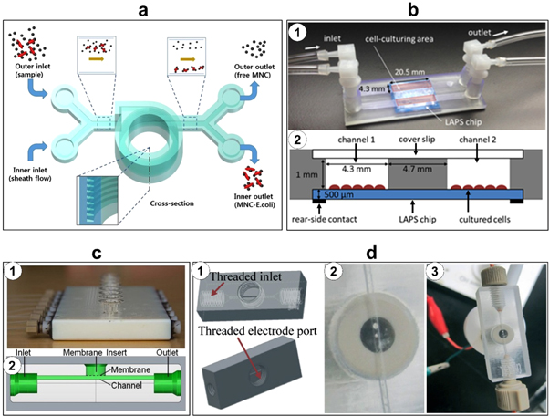
Complete 3D-printed devices have been fabricated for detecting and separating biological components. Krejcova et al demonstrated the fabrication of an optimized biosensor device using paramagnetic particles [7]. The microfluidic device was 3D printed and fitted with electrochemical detection devices. A two-step detection process achieved isolation of hemagglutinin with paramagnetic particles and electrochemical detection of quantum dot-labeled hemagglutinin. More recently, Lee et al have reported a SLA-printed microfluidic device consisting of a helical microchannel for detecting pathogenic bacteria (figure 7(a)) [8]. The lab-on-a-chip device featured a trapezoidal cross-section design to avoid the accumulation of particles adjacent to the inner wall of the channels; the device also incorporated an extra inlet to facilitate sheath flow, which allowed complete separation of particles. The authors used antibody-functionalized magnetic nanoparticle clusters which bound to E. coli bacteria from milk, then separated the bound clusters from unbound clusters by particle size, resulting in a detection limit of 10 cfu ml−1 in a buffer solution and 100 cfu ml−1 in milk. Chudobova et al demonstrated a novel 3D-printed microfluidic platform for rapid and accurate detection of Methicillin-resistant Staphylococcus aureus (MRSA), fabricated using a FDM 3D printer with ABS [57]. The study achieved sequential bacterial cultivation, DNA isolation, polymerase chain reaction to amplify the mecA gene, and gene detection using gold nanoparticles as an indicator of MRSA.
Figure 7. 3D-printed microfluidic chips. (a) Schematic of a microfluidic chip for inertial focusing and separation of captured bacteria. Reproduced with permission [8]. (b) 3D-printed microfluidic chip attached to light-addressable potentiometric sensor (LAPS); (1) image of two microfluidic channels with independent inlet and outlet attached to LAPS chip; (2) cross-sectional 3D layout of a 3D-printed microfluidic chip coupled to a LAPS chip with a sensing area of 20.5 mm by 4.3 mm. Reproduced with permission [58]. (c) 3D-printed device for high-throughput drug transport and cell viability study; (1) the final 3D-printed device with adapters for syringe pumps, channels, membranes, and outlets; (2) the side view schematic of the device shows the fluidic channel under the membrane and the location of a commercially available membrane insert on which endothelial cells are cultured. Reproduced with permission [41]. (d) 3D-printed microfluidic device for electrochemical detection; (1) 3D design of the devices; (2) the 3D-printed 0.5 mm-wide channel with the Pt-electrode screwed into the electrode port; (3) the final 3D-printed microfluidic device with the Pt-electrode, electrode leads, and adapters for syringe pumps. Reproduced with permission [37].
Download figure:
Standard image High-resolution image
In addition, the concept of integrated sensing on a 3D-printed microfluidic cell culture device has been proposed. Takenaga et al proposed a microfluidic unit fabricated via SLA 3D printing with transparent resin and assembled on a light addressable potentiometric sensor (LAPS) for chemical sensing (figure 7(b)) [58]. The platform was found to be more conducive to cell growth compared to standard culture conditions. Further, the LAPS system was demonstrated to monitor cellular metabolic activity in terms of electrical potential and pH. As another interesting application, Anderson et al reported a 3D-printed microfluidic device for high throughput drug transport studies [41]. The device contained 8 parallel channels, and each with a porous polycarbonate membrane to study drug transport across the membrane (figure 7(c)). When pumping levofloxacin and linezolid through the channels, the device allows approximately 18%–21% of the drug to reach cells cultured in the wells above, which can be useful to study the effects of drugs on cells.
Electrodes have also been integrated into complete 3D-printed microfluidic devices for various sensing applications. Erkal et al have investigated the fabrication of two reusable 3D-printed microfluidic devices with the capability of housing different electrodes (carbon, platinum, gold, and silver) for various electrochemical applications such as neurotransmitter detection, nitric oxide detection, and measuring oxygen tension in a stream of red blood cells [37]. In order to fabricate the electrodes, the desired materials were cut into different sizes and then inserted into a polyetheretherketone fitting nut. The first printed device was a microfluidic platform with 500 μm × 500 μm straight channels and threaded printed ports for inserting the nut and electrodes which were used for nitric oxide (with 1 μM limit of detection) and dopamine detection (with a 500 nM limit of detection) (figure 7(d)). The second printed device was a platform with 7 mm by 3 mm by 0.5 mm channels containing Nafion-coated Ag/AgCl electrodes and two trans-well membranes used for measuring the oxygen tension and ATP, respectively, in red blood cell streams. In another study, Vlachova et al formed a 3D-printed microfluidic chip for electrochemical detection of hydrolysed micro RNA using FDM 3D printing with ABS material [59]. The device had two chambers, one for the hydrolysis of nucleic acids and another for the electrochemical detection of nucleobases using replaceable glassy carbon electrodes.
4. Materials for 3D-printed microfluidics
It is essential to understand the 3D printing material properties due to their impacts on the fabrication process, post processing, and applications of 3D-printed microfluidics. Material considerations are also important mainly because of the ever-growing trend of 3D printing technologies and availability of new materials which are yet to be standardized. Given the fact that we have not reached to this standardization yet, material properties of current raw materials available for numerous 3D printers are discussed here for better application of these technologies to microfluidics.
Biocompatibility, transparency, printability, viscosity, and elastic modulus, are of the most pertinent of these properties which allow researchers to select the most appropriate materials for their device function. Elastic modulus is the mechanical relationship between stress and strain, which is of extreme importance in designing pieces such as channels and valves which must withstand high fluid pressure. Although microfluidics deals with such small quantities of fluid, the pressure generated from pumping through these devices can be enough to cause an elastic deformation in the channel or valve that is integral in regulating the microfluidic process [60].
In microfluidic applications, transparency of materials is also a useful property to consider. In microfluidics, visual observations are necessary to ensure the reagents are interacting properly and flowing appropriately. In addition, in biological applications of microfluidics, cells may be imaged using either transmitted light or epifluorescence. PDMS is commonly used for fabricating microfluidic devices due to its excellent transparency. Although PDMS is widely known for its excellent optical transparency [61], many 3D-printable resins have been shown to exhibit comparable transparency (tables 1 and 2). However, it should be noted that due to the light-polymerization method involved in SLA 3D printing, particularly in the case of transparent resins, there can be an issue with unintentionally curing layers above the layer being printed. UV blockers are often added to the resins to prevent this issue, but these blockers can cause a high level of light reflection, limiting the ability to image fluorescent molecules in low wavelengths.
Table 1. 3D-printable commercial materials.
| Company (Printer) | Material | Elastic modulus (GPa) | Tensile strength (MPa) | Transparency |
|---|---|---|---|---|
| N/A | PDMS (Sylgard 184) [61, 66] | 0.001 32–0.002 97 | 3.51–7.65 | Standard for comparison |
| MakerBot | Polylactic acid | 3.368 [67] | 56.6 [67] | Available |
| Acrylonitrile butadiene styrene (ABS) | 1.807 [67] | 28.5 [67] | Unavailable | |
| Formlabs | Polymethyl methacrylate | 2.7 [68] | 61.5 [68] | Available |
| Asiga (Pico Plus) | PlasCLEAR polypropylene/acrylnitril-butadien-styrol [58] | — | 52.6 [69] | Available [69] |
| Stratasys (Objet Connex 350) | Objet Vero White Plus | 2–3 | 50–65 | Opaque, |
| Isobornyl acrylate (15%–30%) | [70] | [70] | However, the objet series offers a transparent material. | |
| Acrylic monomer (15%–30%) | ||||
| Urethane acrylate (15%–50%) | ||||
| Epoxy acrylate (5–10; 10%–15%) | ||||
| Acrylic monomer (5–10; 10%–15%) | ||||
| Acrylic oligomer (5–10; 10%–15%), and photoinitiator (0.1–1; 1%–2%) [41] | ||||
| 3DSystems (ProjetHD3500) | VisiJet M3 acrylonitrile butadiene styrene [47] | 0.866–2.168 [71] | 20.5–49 [71] | Available |
| Somos | WaterShed XC (Proprietary) [53] | 2.77 | 50.4 | Available [72] |
| MiiCraft | Modified acrylate 5%–30% | — | — | Available |
| Modified acrylate oligomer 5%–30% | ||||
| Acrylate momoner 20%–60% | ||||
| Epoxy monomer 5%–30% | ||||
| Photoinitiator & additives 2%–10% [73] |
Table 2. 3D printable custom-developed materials.
| Transparency | Mechanical Properties | Other Properties | Reference |
|---|---|---|---|
| Not transparent, orange color | Not elastic, rigid with strong bonding strength | Can be used with nucleic acids and stable when in contact with chemical reaction | [13] |
| Colorless, 60% transmittance, transparent | Non-flexible | Biocompatible and hydrophobic; can be used for mixing and electrophoresis | [2] |
| Transparent after sanding and channel treatment, PDMS or polystyrene coating improved transparency | Non-flexible | Biocompatible, non-toxic, and safe for cell cultures; can be used for electrolysis | [43] |
In general, SLA resins are designed to polymerize under a specific wavelength (often in the UV range), making cross-compatibility between resins and 3D printers limited. Moreover, resin viscosity is an important parameter in choosing an appropriate method for removal of uncured resin from 3D-printed channels. The printing resolution also depends on materials. Due to differences in material properties, a single device may have slightly different dimensions when printed on different types of 3D printers [37]. On the other hand, in the case of FDM materials, it is important to consider the bonding strength between the layers. FDM printers also require solid support materials, some of which can be difficult to remove post-printing, limiting the minimum channel size.
Microfluidic applications often involve biomaterials or chemical reagents. Chemical composition of the resin is critical to make the 3D-printed devices a viable option [2, 13, 43]. Devices should be made of resins which will not react with or absorb protein and nucleic acid reagents to be useful in biomedical applications. Similarly, resins should be biocompatible, as living cells may come into contact or be cultured in close proximity with the resin [13]. The biocompatibility and transparency of both SLA and multi-jet resins have been shown to be sufficient for biological experiments [18].
In light of highly favorable properties of existing resins as well as active innovation in this area, use of 3D printing materials to create microfluidic devices has gained popularity. The properties of several 3D-printable commercial and custom-made materials are listed in tables 1 and 2, respectively. With varying properties from material to material, a researcher should consider each of these properties when choosing a material for a particular application.
5. Discussion
3D printing has gained significant popularity for a myriad of applications in several fields. One such application with recent success as well as future promise is microfluidics. Using 3D printing offers a key benefit that the entire device can be fabricated in one step compared to UV lithography and soft lithography of PDMS molds which require a bonding step to fabricate the device [54]. 3D printing of microfluidic devices for use in various research domains has several advantages over the existing microfabrication tools including accessibility, low cost, efficiency, versatility, and rapid prototyping. Several challenges remain, including choice of materials and limitations on the smallest channel dimensions which may be fabricated. Nonetheless, 3D printing shows promise to add broad and novel applicability to several research domains in the coming years.
Here, we present a wide range of technologies available for 3D printing and highlight those which have been applied to microfluidics thus far. While there are advantages and drawbacks to each of these methods, there may be value in applying 3D printing technologies which have not yet been used for microfluidic fabrication. High resolution and precision has been achieved in microfluidic devices with photopolymer jetting 3D printers. However, other techniques such as binder jetting and laser sintering offer the advantage of not requiring fixed support structures, which can be difficult to remove following the photopolymer jetting process. Further, taking advantage of a modular fabrication and assembly approach, different components may be printed with different printers and materials. For example, flexible parts may be printed with one type of 3D printer and more precise parts may be printed with another, followed by assembly of the modules.
Integration of functional components directly into the printed devices is a capability unique to 3D printing fabrication. However, while many reported 3D-printed devices consist of passive components which enable control over fluid flow through the device, only a few active microfluidic components have been reported in the literature. Active components can enable additional control and complex capabilities to microfluidic devices, further expanding the sophistication of 3D-printed lab-on-a-chip devices. This gap represents a promising direction for future advancement of 3D-printed devices and implementation of more complex and useful processes [2].
Although 3D printing technology offers great advantages to the field of microfluidics, it is important to note a variety of factors and limitations such as resin material and printing resolution when considering the shift from traditional fabrication techniques to 3D printing. The variety of printable materials with appropriate mechanical, electrical, chemical and optical properties remains limited to those commercially available. In some cases, there is a lack of suitable material for particular applications [61]. For example, some of the available colorless resins' transmittance are not sufficient for high resolution on-chip optical imaging [2]. Further, their biocompatibility [63] and gas permeability are hindering factors for long-term on-chip cell culture [11]. Moreover, use of non-proprietary resins in most commercial printers requires optimization and expertise. However, with the increasing popularity of 3D printing, the outlook for this challenge is promising. In 2015, Autodesk released the formulation for their previously proprietary Standard Clear Prototyping resin under a creative commons license, challenging customers to 'understand how it works, make changes, make it better, and share those changes' [64]. Open source initiatives such as this one tend to spur innovation in the field, as suggested by table 2, opening the door for rapid advancements in the availability of 3D-printable materials in the coming years.
Choice of the appropriate commercial 3D printer for fabricating microfluidic devices depends on several considerations: resolution, processing time, and printing dimensions. High resolution printers are able to fabricate channels with smaller sizes, superior surface finishes and high precision. However, printers with high resolution tend to fabricate devices with smaller layer heights, and therefore have lower throughput. Yet, even with the ability to print features as small as tens of microns, the printer resolution is not the only effective factor in achieving micron-scale channel dimensions: channel dimensions can also be limited by the printing mechanism [2, 11, 65]. FDM printers generally rely on support materials during printing which must be removed from the channel following the printing process, limiting the size of channels which may be cleaned. SLA printers use liquid resin which can be more easily removed using a solvent. However, the use of light to cure each layer combined with the use of transparent materials introduces the issue of 'overcuring', in which the light applied for photopolymerization of one layer may unintentionally spill over to the opposite layer. This effect can cure resin within a channel and again limit the channel size. As printing resolution and cost are positively correlated, the price of the printer and materials, and therefore the cost incurred to fabricate microfluidic devices, must be balanced with the desired resolution [2, 13].
Considering the significant progress in the field thus far as well as the current limitations, the process of incorporating 3D printing within microfluidics is still in its infancy. However, several studies have shown promising applications of 3D printing to microfluidic platforms (table 3). Results of these studies confirm that 3D printing procedures for creating microfluidic devices are relatively fast and simplify the labor required for photo and soft lithography-based techniques into a one-step fabrication process. Further, 3D printing makes the fabrication of devices with highly complex 3D features more feasible and efficient. Developing 3D printing technologies and increasing the versatility of materials has the potential to significantly affect the way microfluidic lab-on-a-chip devices are fabricated. Application of rapidly improving 3D printing technology has already made microfluidics more accessible to basic scientists and engineers alike. Future improvements to 3D printing technology and materials for microfluidics is likely to spur further advancements in several fields of research.
Table 3. Metric comparison, advantages, and limitations of 3D-printed microfluidic applications.
| Performance metric | Micro-channels with integrated structures (i.e. valves) [12, 13, 54] | Magnetic field controllable microfluidic chip [7] | 3D- printed masters for PDMS molding [11] | Microfluidic devices for electro-chemical detection [37] | Microfluidic devices for separation of pathogens by inertial focusing [8] |
|---|---|---|---|---|---|
| Fabrication material | Resin, poly-propylene | Polylactide (PLA) | Resin | Acrylate-based polymer | Resin (DSM SomosWaterShed XC 11122) |
| Fabrication time | <1 h, 2–4 h | 94 min | >4 h | Several hours | N/A |
| Advantages | Rapidly redesign and print, one step fabrication | Rapid detection | Used in novel injection-on-demand devices | Reusability, transferability, flexible dimension | Selectivity, the least damaging effect on living cells, no need for external force |
| Limitations | Fatigue occurrence, leakage, resin modification | Isolation step before detection | Post treatment for 3D-printed masters, suitable peeling direction | Electrode material modification | N/A |
Acknowledgments
ST acknowledges the American Heart Association Scientist Development Grant (15SDG25080056), the University of Connecticut Research Excellence Program award and the University of Connecticut 2015 Provost's Teaching Innovation Mini Grant award for financial support of this research. The authors acknowledge Keeyan Ghoreshi for his research to prepare table 2. The authors also acknowledge Chu Hsiang Yu's artful contributions for figure 1.
Footnotes
- 6
The Woodblock image has been obtained by the authors from the Wikimedia website where it was made available by Vmenkov under a CC BY-SA 3 license. It is included within this article on that basis. It is attributed to China Block Printing Museum inYangzhou. The Diamond Sutra image has been obtained by the authors from the Wikimedia (https://commons.wikimedia.org/wiki/File:Diamond_sutra.jpg) where it is stated to have been released into the public domain. It is included within this article on that basis. The moveable typeset has been obtained by the authors from the Wikimedia website where it was made available by Uploadmo under a CC BY-SA 3 license. It is included within this article on that basis. It is attributed to Uploadmo. The Gutenberg's printing press image has been obtained by the authors from the Wikimedia (https://commons.wikimedia.org/wiki/File:Gutenberg.press.jpg) where it is stated to have been released into the public domain. It is included within this article on that basis. The stone lithography press image has been obtained by the authors from the Wikimedia website where it was made available by Chris 73 under a CC BY-SA 3 license. It is included within this article on that basis. It is attributed to Chris 73. The Stanhope press image has been obtained by the authors from the Wikimedia website where it was made available by Bubo under a CC BY-SA 3 license. It is included within this article on that basis. It is attributed to Selbst Fotografiert.