
Abstract
Developing an improved understanding of the interaction between the immediate roof and the rockbolts is fundamental in obtaining an effective roof support system. Effective instrumentation along the full length of fully grouted rock bolts would provide the required understanding, which in turn could improve the rock related safety in the underground mines. The rock bolt sensing technology has rapidly developed in the last decade, where the instrumentation has changed from short electrical strain gauges to optical strain and shape sensing using more than 2 slots (which used to be the standard). In addition, the instrumentation has been increased from two orthogonal slots to three or four. With these recent advances of the technologies, there lies a challenge in analysing and understanding the new type of data and in effectively adopting the new technology into the underground mines. This paper deals with the challenges of instrumenting rock bolts with fibre optics and presents techniques for improving the existing technology. Furthermore, it includes a prototype design for an effective implementation of this technology to better suit the harsh underground environment.
1 Introduction
Understanding the response of rockbolts along their total length in situ, is essential: to monitor the effectiveness of installed support systems, to improve support design, support modelling practices, and in a larger context, the design of underground excavations. Current designs of rockbolt support considers only the bolt tensile strength, diameter, length, grade, thickness of the annulus (if resin grouted), and the interaction of the rock with the support unit. Very few similar design considerations that are inclusive of the shear- or bending-mechanism exist and none are widely used in the industry (Li 2017). An example showing the way a combined load affects rockbolts is shown in Fig. 1. In in situ, there are usually many more shear zones as a result of rock movement associated mainly with bedding, joints and faults. It is interesting to note that in the only international standard that addresses mine rockbolt testing (ASTM F432), shear and bending loads are still not even mentioned.

Loading mechanisms along a rockbolt in situ. Pure axial (a), shear and bending (b), combined loading (c) (Kostecki and Spearing 2019)
2 Historical Instrumented Rockbolt Trials
To develop an understanding of how rockbolts behave under load, instrumentation of the rockbolts were developed. With adoption of each technology for instrumentation, there were advantages as well as challenges. This paper aims to provide background to better understand the in-situ rockbolt behaviour using improved design to measure strain and 3D deformation of rockbolts.
Early research studying the effectiveness of mechanical rock bolts was undertaken in the US by Barry et al. (1954). A torque wrench was used to determine bolt loads and they also developed the first version of a rock bolt pull test apparatus that is now routinely used in the industry. Instrumented rock bolts can be used to evaluate the rock bolt performance in situ by measuring the amount of strain the rock bolt is undergoing. Instrumented rock bolts with strain gauges were first used by Sawyer and Karabin (1975) to measure strain in rock bolts.
Freeman (1978) started studies on roof monitoring using short-length resistive strain gauges. Later, Signer developed studies to monitor the roof movements in coal mines from 1984 to 1997 at NIOSH (Serbousek and Signer 1984; Signer 1988; Signer et al. 1993, 1997). These studies performed successfully at monitoring axial strain at that time while little emphasis was given on shear strains. Signer and Lewis (1998) stated that the axial load is the primary load in steel bolts, but in some situations, a combination of axial, bending, and/or shear force can cause bolt failure. However, most of the studies until recently were focused on the axial strain only.
Most of the experiments conducted until 2013 used two opposite slots to place short-length resistive strain gauges. Spearing et al. (2013) pointed out the ineffectiveness of instrumented rock bolts using short-length resistive strain gauges in which no more than 10% of the bolt length was monitored. Increasing the number of strain gauges would also raise the costs making it unaffordable since the strain gauges are expensive. Furthermore, a two-slot instrumented bolt can only measure the shear direction if the slots are oriented in the direction of shear.
2.1 Short Strain Gauges
According to Hyett and Spearing (2012), all previous attempts at monitoring rock bolt loads had concentrated on short base-length (typically < 20 mm) strain gauges adhered into two orthogonal grooves machined along the length of the bolt as shown in Fig. 2.

A rockbolt with two orthogonal slots (to adhere strain gauges into)
The interpretation and analysis of the data using this method is not included in this paper.
An extensive body of experimental and development research using short strain gauged rebar has been conducted in the US over a 30-year period principally by NIOSH (Signer and Jones 1990; Signer et al. 1993, 1997) and its predecessor, the United States Bureau of Mines. Signer and Jones (1990) tested fully grouted roof bolts with strain gauge instrumentation in two slots.
There are critical shortcomings associated with this instrumentation approach, including:
-
Typically, less than 10% of the total bolt is monitored and hence peak loads can be underestimated due to their location or overestimated due its localized measurement.
-
The data loggers are not intrinsically safe, which results in a delay for readings between the installation and the first reading in coal mines.
-
Shear and bending was often missed or underestimated and the direction could not be reliably established.
2.2 Long Strain Gauges
An alternative approach was proposed by Spearing et al. (2011) based on an array of long displacement sensors with length typically around 300 mm. Three long base-length strain gauges were arranged in each of the two diametrically opposed slot so that almost the entire length of the bolt was monitored. Two different configurations termed stacked and staggered were used as shown in Fig. 3.

Sketch showing stacked (a) and staggered (b) long strain gauge configurations (Spearing et al. 2011)
The results showed that staggered long base-length strain gauges are more effective in monitoring shear and bending as the stacked configuration could effectively cancel out the shear couplet caused due to shear. Long base-length measurements will therefore capture the deformation due to any discrete points of loading, but due to an averaging effect it does however underestimate the extreme values especially if the strain profile varies dramatically.
2.3 The Effectiveness of Strain Gauges in Two Slots
The number, length and positioning of the strain gauges are important in resin grouted rock bolts monitoring, because typically a ten cm resin column can hold over three tons of axial load. This becomes significant because an induced parting (an opening along a discontinuity or fracture) in the immediate roof strata, can cause a significant localized load that may be partially (or even totally) missed by the array of gauges as:
-
Depending on the relative orientation of any rock lateral/shear movement to the slots, the bending or shear could be significantly under-estimated or cannot be captured.
-
Short gauges may not be located near enough to the opening vicinity and the support generated by the resin column either side of the opening could mask the actual load.
-
Long gauges that intersect the opening would record an average load over the gauge length and hence possibly miss the peak and the load shedding in the resin column.
Even more critical is the need for more than two slots to be able to capture the shear and bending magnitudes and directions in rock bolts.
2.4 The Need for a Third Slot
Kostecki et al. (2016) conducted an extensive set of simple laboratory tests to compare the results obtained from instrumented rock bolts with 2 and 3 slots as shown in Fig. 4. The laboratory tests included repeated axial, shear and simple three-point bending tests with the setup shown in Fig. 5. The instrumentation technologies used were a long base-length displacement sensor technology and two optical fibre technologies. All tests were repeated several times for reliability and redundancy considerations. From these tests it was found that at least three slots were required to adequately measure the shear and bending loads on the rock bolt if the directions of the applied load is not pre-determined. Two slots bolt can only measure correct shear and bending loads if the orientation of the slots to the direction of load is known. This would not be possible in an in-situ test. This is also logical as to measure stress in situ 3-gauge strain rosettes are used at typically 0°, 45° and 90° or 0°, 60° and 120° (delta configuration).

Two and three slot orientations of the instrumented bolts

The laboratory test rig used
The optical fibre sensing technologies used during these trials were:
-
Fibre Bragg Gratings (FBG), and
-
Distributed Optical Sensing (DOS) technology based on Rayleigh backscatter.
The optical fibre is normally made of glass and designed to transmit light along its length, traditionally for telecommunication purposes. According to Jessu et al. (2016), the FBG sensor uses Bragg reflectors to measure the strain at certain points along the fibre, while the DOS technology allows continuous strain measurements throughout the fibre length. Here small amounts of light are reflected back from tiny imperfections in the glass, creating a “fingerprint” for each section of fibre. The interrogator uses a pulsed and tunable laser to sweep through its frequency range. Changes are detected when it goes through characteristics fingerprints along the fibre length, based on time of flight, and this is then converted to strain. The advantage of using this technology is the improvement of the instrumentation with highest resolution (strain measurements every 0.5 mm).
The optical fibre technology was supplied by Yieldpoint (Hyett et al 2013). This research established a new feasible technology and system of using 3 slots to effectively measure the specific loads continuously or at small intervals (less than a few cm) (combination of shear, axial, and/or bending) along the length of a grouted rock bolt.
3 Early Underground Trials in US Coal Mines Using Optical Fibre Instrumentation
Field studies with optical fibre technologies were conducted in a shallow (about 40 m deep) room and pillar coal mine and a deeper (about 200 m) room and pillar coal mine in Illinois Basin (Jessu et al. 2016; Spearing 2015). The instrumented rockbolts were #6 (19 mm diameter) grade 60, 122 cm long and were installed as secondary supports in a crosscut behind the current excavation. Fibre Bragg Grating and Distributed Optical Sensing technologies were mounted in the rockbolts with two and three slot orientations with the slot width and depth of 3 mm × 3 mm. Fibre Bragg sensors were positioned in the two and three slot instruments in such a way that the sensors were placed 20 cm apart (5 sensors in each slot) from each other and approximately aligned in a stacked configuration. Distributed Optical Sensing technology has a very high spatial resolution which can measure up to 3 points in a centimetre (about 900 points along one slot), and the fibre was looped between the slots. The looping and effectively using a single fibre in all 3 slots was found to be a disadvantage as if the fibre was damaged it effected all the readings after the damaged area. Using 3 or 4 independent fibres in 3 or 4 respective slots makes the instrumented rockbolt less prone to loss of effectiveness.
In the first trial, the fibre in the instrumented rockbolt protruded out of the rockbolt head and was connected directly to the data loggers as shown in Fig. 6a. Therefore, these rockbolts were manually installed in the drill hole approximately 25 mm longer than the bolt by pumping up the resin. The challenges in manually installing the rockbolts in the first trial led to mounting the connectors on the rockbolt head in the second trial as shown in Fig. 6b. After the rockbolts were installed and external fibre was used to connect the instrumented rock bolt to the data logger as shown in Fig. 6c.

Instrumented rockbolts in a first trial, b connectors in second trial and c external fibre connecting the instrumented cable to data logger
Instrumented rockbolts were monitored for a period of two weeks in the first in situ trials and for a month in the second in situ trials. Result of one of the instrumented rockbolt with three slots mounted with Fibre Bragg Grating technology is shown in the Fig. 7 (Spearing 2015). The instrumented rockbolt shows the strain values in all three slots which can then be analysed for location of axial, shear or combined loading of the rockbolt. It is also obvious that the instrumented rockbolt with three slot orientation would provide with not only the magnitude but also the direction of loads which can also be used for rendering a 3-dimensional visualization of the rockbolt.

Representation of the instrumented rockbolt with bending and axial loads in situ
4 Shortcoming and Lessons Learnt from the Underground Trials
The current shortcomings of these first trials were found to be:
-
Although different data loggers are used for the two presented sensing methods, both are costly and in the case of DOS, the data logger needs to be manually read. This means that it is manpower intensive in order to collect data regularly. Hopefully, this will change as the need and demand for such technology with rock bolts increases.
-
The data loggers were fragile and at the time a ruggedized version was not available.
-
A single optical fibre was used during the trials, with the sensing fibre looped across the slots in the bolt. Although this enabled the use of a standard fibre connector in the second set of trials, it let to confusions in the alignment of recorded data along the length of the bolt. Furthermore, it created a single point of failure as the data couldn’t be analysed anymore if a breakage occurred anywhere in the fibre during installation or as a result of a high stress event.
-
Properties of the bolt are altered by the slotting presented so far. This has always been the case with instrumentation along rock bolts, but a third slot as used in the trials increased this effect even more.
-
The temperature needs to be measured every time strain readings are measured as the optical fibre’s results are extremely temperature sensitive. In these first trials temperature was not recorded as it was not known to be a major parameter. This was however not too significant as the temperature in a mine area remains relatively constant.
-
Errors can be introduced due to imperfections in the instrumented rock bolt manufacturing process (Hoehn and Olsson 2018). Figure 8 shows an example these imperfections, which include, but are not limited to:
Fig. 8 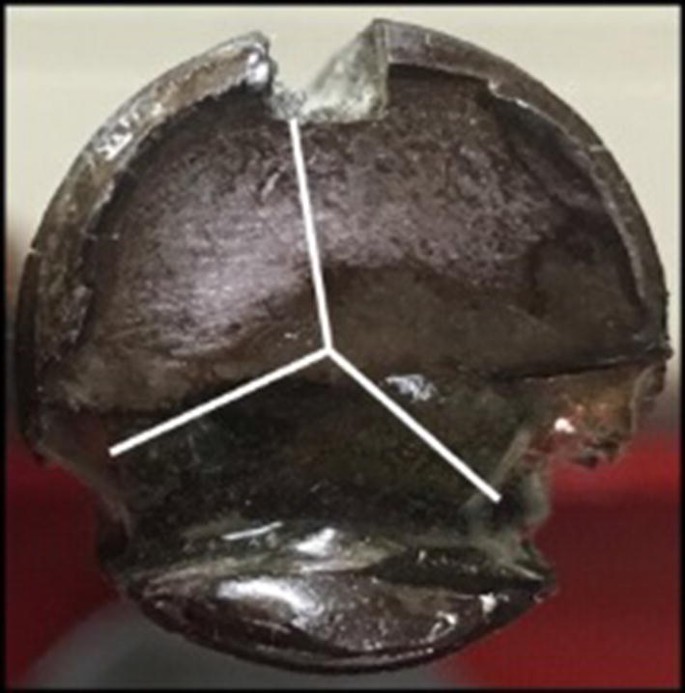
Incorrectly angled slot during manufacturing
-
Slot orientation misalignments,
-
Slot depth variations,
-
Optical fibre placement inaccuracies when positioning the 0.2 mm thick fibre in a 3 mm wide slot, and
-
Optical fibre connections causing unwanted reflections and losses.
-
-
-
Challenges during installationt
-
In the first set of underground trials, the fibre protruded of the rockbolt head had to be manually installed which makes it unworthy of the commercial use in the industry.
-
In the second set of underground trials, the connectors were attached to the bolt head to install the rockbolt with the help of rock bolter. The connectors were often damaged during the removal of the rockbolt bit after installation of the rockbolt due to the spring energy.
-
Issues obtaining reliable results caused by manually taking readings and omitting temperature compensations.
-
Data monitoring in gassy (coal) mines as the equipment is sensitive to dust and not rated intrinsically safe.
-

5 Improved Instrumented Rockbolt Design
An improved design for instrumented rockbolts has been developed in the Instrumented Rock Bolt Project funded by the Mining3, Minerals Research Institute of Western Australia, Curtin University and Peabody Energy to address the above-mentioned issues that include the following enhancements.
5.1 Number of Slots
Four slots were cut at 90° to each other, each containing a separate fibre. This improves the reliability and accuracy of the instrumentation and even if one fibre fails the other three continue to provide sufficient information to analyse the in-situ rockbolt condition.
5.2 Slot Shape and Depth
The insertion of slots effects the structural properties of the bolt, so to minimize this effect, only shallow slots of 0.5 mm depth were machined. Further, different slot shapes were also tested for various parameters like ease of machining, accuracy of fibre placement, and effect on structural integrity of bolt (Fig. 9).

Test plate for various slot shape and depth experiments
5.3 Slot Alignment (Accuracy)
To ensure the slots were machined perfectly perpendicular to each other a special mounting plate was designed to hold the rockbolt in place. This also allowed the machining at consistent depth as it straightened the rockbolts during machining, which often have a “natural” curvature exceeding the desired slot depth (Fig. 10).

Slot machining
5.4 Fibre Bolt Connectors
The mining environment is known to be dusty, which poses a challenge for optical sensing systems. Therefore, the optical connectors shown in Fig. 6, commonly used in telecommunication applications, were replaced with a small 4-channel, harsh environment connector, specifically modified to fit this application.
Further, the fibre routing was designed to contain a section of the sensing fibre not being exposed to strain, caused by rock movements, but only to measure the environment temperature. Measurements from this section can be used by the software to perform a temperature compensation for the strain readings of the other parts of the rockbolt (Fig. 11).

Connector embedded/recessed in rockbolt
5.5 Fibre Fitting
To eliminate possible variabilities caused through manual integration of the optical fibres into the rockbolts a 3-axes gantry system was used to apply the glue in the fibre slot and cure it via an attached UV light (Fig. 12).

Fibre fitting process
5.6 Fibre Sensing Technology
The early underground trials demonstrated the need of a high spatial resolution combined with a robust data read-out system. FBG sensing systems offer robustness, but lack the spatial resolution, while Rayleigh backscatter system offer high spatial resolution at the cost of being very sensitive. Further, they require regular calibrations and manual read-outs but only offer a small sensing range compared to FBGs.
A solution was found by using a Continuous Bragg Grating, or All Grating Fibre (AGF) System. This technology offers the robustness of the FBG approach, and still provides a strain measurement for every 5 mm along the fibre, with a strain measurement range of approximately 15,000 . An AGF contains a continuous Bragg Grating along the entire fibre length to determine the strain. The grating is weaker though than a typical FBG grating to ensure that not all light is reflected at the first portion of the grating and a response from the entire fibre cable length can be received. Therefore, the interrogator needs to be more sensitive than a typical FBG interrogator. Further, the light source is pulsed thus the location along the fibre can be determined by time-of-flight. Cost-wise an AGF system is located half way between a typical FBG and Rayleigh backscatter system.
6 Effectively Obtaining Results Underground
The purpose of the instrumented rockbolt is to sense the strain as a vector along the entire length of the bolt and report the values to a data logger. These readings can be computed into 3D bolt deformation values in real-time. The advantage of a fibre optic sensing system is that there is no need to run copper cables down the mine and that the sensor part is intrinsically safe by design. Further, the Control PC can be located at a distance, e.g. above ground to manage the data acquisition. However, there are still additional components required to operate the fibre sensing system.
The Mining3 instrumented rockbolt uses optical sensing fibres, containing continuous fibre grating, which need to be connected via a Broad-Band Reflector (BBR) to a Fibre Interrogator. The optical fibre lead cable can be up to 1 km long for remote installations and the BBR, a passive optical device, will inform the interrogator where the sensing elements starts. The distance between the BBR and the rockbolt is currently 15 m maximum. To reduce the number of lead cables it is possible to utilise a Fibre Switch before the BBR to multiplex between different rockbolts. However, as each bolt contains 4 sensing fibres all 4 fibres need to be switched simultaneously to measure the strain on all fibres at the same time. Fibre switches are available in various configurations and for the Instrumented Rockbolt project a RS232-controlled 4-by-48 channels (to connect to 12 instrumented rockbolts) was selected. Fibre Switches requires only very little power (less than 1 W) and it is possible to run them off a battery, which will compromise the intrinsic safety of the system, or through a Power-over-Fibre (PoF) system as shown in the block diagram below, Fig. 13. PoF systems are commercially available from various manufactures like the MH GoPower Photovoltaic Power Converter system.

System block diagram
7 Conclusion and Future Work
This paper presents an improved design and system configuration of an instrumented rockbolt system to measure strain and 3D deformations of rockbolts with the aim of developing a better understanding of the in-situ rockbolt behaviour. The shortcomings and disadvantages of the existing optical fibre instrumented rockbolt design have been identified. Modifications in the design have been implemented to improve the accuracy, reliability and ease of installation of the instrumented rock bolts. Improvements have also been applied in the data transmission and recording methods to make the system more practical to be used in an underground mine. The new design has already been tested successfully and consequently the first series of underground trials of the new design is currently being conducted.
References
ASTM F432-13 (2013) Standard specification for roof and rock bolts and accessories. ASTM International, West Conshohocken, PA. www.astm.org.
Barry AJ, Panek LA, McCormick JA (1954) Use of Torque Wrench to determine load in roof bolts: part 2: expansion-type 3/4-inch bolts. US Bureau of Mines, Report of Investigations, RI5080
Freeman TJ (1978) The behaviour of fully-bonded rock bolts in the Kielder experimental tunnel. Tunn Tunn Int 10(5):37–40
Hoehn K, Olsson A (2018) 3D shape sensing of elongated objects using fibre bragg gratings. Mechatronics and machine vision in practice 3. Springer, Cham, pp 3–14
Hyett A, Spearing AJS (2012) New technology for measuring the in situ performance of rock bolts. In: 46th US rock mechanics/geomechanics symposium. American Rock Mechanics Association, Jan 2012
Hyett A, Forbes B, Spearing S (2013) Enlightening bolts: using distributed optical sensing to measure the strain profile along fully grouted rock bolts. In: Proceedings of the 32nd international conference on ground control in mining, Morgantown, WV, 30 July–1 Aug 2013, pp 107–112
Jessu KV, Kostecki T, Spearing S (2016) Measuring roof-bolt response to axial and shear stresses: laboratory and first in-situ analyses. CIM J 7(1):62–70
Kostecki TR, Spearing AJS (Sam) (2019) Design methods for rock bolts using in-situ measurement from underground coal mines. Southern Illinois University Carbondale
Kostecki TR, Spearing AJS, Forbes B, Hyett A (2016) New instrumented method to measure the true loading profile along grouted rockbolts. SME transactions, January.
Li CC (2017) Principles of rockbolting design. J Rock Mech Geotech Eng 9(3):396–414
Sawyer S, Karabin G (1975) The development and use of resin instrumentation for the in-situ measurement of axial loads in fully resin-grouted roof bolt. In: Proceedings of the 1st symposium on underground mining, pp 90–103
Serbousek MO, Signer SP (1984) Load transfer mechanics in fully-grouted roof bolts. In Proceedings, 4th International Conference on Ground Control in Mining
Signer S (1988) Comparative studies in the mechanics of grouted roof bolts. In Proceedings of the 7th International Conference on Ground Control in Mining, vol 7, pp 282–288
Signer SP, Jones SD (1990). A case study of grouted roof bolt loading in a two-entry gate road. In: Proceedings of the 9th international conference on ground control in mining. West Virginia University, Morgantown, WV, June 1990, pp 35–41
Signer SP, Lewis JL (1998) A case study of bolt performance in a two-entry gateroad. In: Proceedings of the 17th international conference on ground control in mining. West Virginia University, Morgantown, WV, pp 249–256
Signer SP, Mark C, Franklin G, Hendon G (1993). Comparisons of active versus passive bolts in a bedded mine roof. In: Proceedings of the 12th international conference on ground control in mining. West Virginia University, Morgantown, WV, August, pp 16–23.
Signer SP, Cox D, Johnston J (1997) A method for the selection of rock support based on bolt loading measurements. In: Proceedings of the 16th conference on ground control in mining. West Virginia University, Morgantown, WV, pp 183–190
Spearing AJS (2015) The precise monitoring of rockbolt performance underground—Final technical report. Unpublished manuscript, Alpha Foundation, Philadelphia, PA, USA.
Spearing AJS, Gadde M, Ray AK, Reisterer J, Lee S (2011) The initial performance of commonly used primary support on US coal mines. In: Proceedings of the 30th international conference on ground control in mining. West Virginia University, Morgantown, WV, pp 183–190.
Spearing S, Hyett A, Kostecki T, Gadde M (2013) New technology for measuring the in situ performance of rock bolts. Int J Rock Mech Min Sci 57:153–166
Acknowledgements
This work was supported by the Minerals Research Institute of Western Australia (MRIWA), Mining3, Curtin University and Peabody Energy.
Author information
Authors and Affiliations
Corresponding author
Additional information
Publisher's Note
Springer Nature remains neutral with regard to jurisdictional claims in published maps and institutional affiliations.
Rights and permissions
Open Access This article is licensed under a Creative Commons Attribution 4.0 International License, which permits use, sharing, adaptation, distribution and reproduction in any medium or format, as long as you give appropriate credit to the original author(s) and the source, provide a link to the Creative Commons licence, and indicate if changes were made. The images or other third party material in this article are included in the article's Creative Commons licence, unless indicated otherwise in a credit line to the material. If material is not included in the article's Creative Commons licence and your intended use is not permitted by statutory regulation or exceeds the permitted use, you will need to obtain permission directly from the copyright holder. To view a copy of this licence, visit http://creativecommons.org/licenses/by/4.0/.
About this article

Cite this article
Hoehn, K., Spearing, A.J.S.(., Jessu, K.V. et al. The Design of Improved Optical Fibre Instrumented Rockbolts. Geotech Geol Eng 38, 4349–4359 (2020). https://doi.org/10.1007/s10706-020-01246-0
Received:
Accepted:
Published:
Issue Date:
DOI: https://doi.org/10.1007/s10706-020-01246-0