The Capo Castello Shear Zone (Eastern Elba Island): Deformation at the Contact between Oceanic and Continent Tectonic Units

Department of Earth and Geo-Environmental Sciences, University of Bari, Piazza Umberto I, 1, 70121 Bari BA, Italy
Geosciences 2020, 10(9), 361; https://doi.org/10.3390/geosciences10090361
Submission received: 19 August 2020
/
Revised: 3 September 2020
/
Accepted: 7 September 2020
/
Published: 10 September 2020
(This article belongs to the Special Issue The Apennines: Tectonics, Sedimentation, and Magmatism from the Palaeozoic to the Present)
Abstract
:Low-grade mylonitic shear zones are commonly characterized by strain partitioning, with alternating low strain protomylonite and high strain mylonite and ultramylonite, where the shearing is most significant. In this paper the capo Castello shear zone is analyzed. It has developed along the contact between continental quartzo-feldspathic, in the footwall, and oceanic ophiolitic units, in the hangingwall. The shear zone shows, mostly within the serpentinites, a heterogeneous strain localization, characterized by an alternation of mylonites and ultramylonites, without a continuous strain gradient moving from the protolith (i.e., the undeformed host rock) to the main tectonic contact between the two units. The significance of this mylonitic shear zone is examined in terms of the dominant deformation mechanisms, and its regional tectonic frame. The combination of the ultramafic protolith metamorphic processes and infiltration of derived fluids caused strain softening by syntectonic metamorphic reactions and dissolution–precipitation processes, leading to the final formation of low strength mineral phases. It is concluded that the strain localization, is mainly controlled by the rock-fluid interactions within the ophiolitic level of the Capo Castello shear zone. Regarding the regional setting, this shear zone can be considered as an analogue of the initial stage of the post-collisional extensional fault, of which mature stage is visible along the Zuccale fault zone, a regional structure affecting eastern Elba Island.
1. Introduction
Mylonites are within shear zones where high strain conditions developed during ductile deformation. Some of the causes of their nucleation can be attributed to: (i) pre-existing mechanical discontinuities [1,2]; (ii) high shear heating [3]; (iii) strain softening caused by fluid-rock interaction and grain size reduction [4,5]. This latter condition favors crystallization mechanisms [6,7], mostly linked to the dissolution–precipitation and diffusive mass-transfer [8,9,10]. There are several cases of strain partitioning in various tectonic settings and at different scales [10,11,12,13,14,15,16]. In the context of collisional and post-collisional evolution of an orogeny, the partitioning of the strain is well evident at the tectonic contact between continental and oceanic units, characterized by quartzo-feldspathic and ultramafic rocks, respectively. This contact commonly develops deformation at temperature conditions up to about 400 °C during collision [17,18]. Furthermore, the presence of syn-tectonic fluids can trigger metamorphic reactions and pressure–solution processes [19], determining the growth of new weak minerals, such as micas, in quartzo-feldspathic rocks and talc, serpentine polymorphs and chlorite, in ultramafic rocks [20,21,22]. Such processes occur in preferential levels where strain tends to be localized ([23,24], even at lower temperature values: 300 °C–500 °C, [25]). In particular, the role of serpentinite alteration tends to deeply weaken ultramafic rocks strength [25,26,27] up to make soft an original highly competent level, leading to the final formation of a phyllosilicate network (for example, formed by talc, muscovite and kaolinite) with a very low frictional strength [28,29,30,31].
In this large context, a further example is from the Capo Castello shear zone, here presented. This shear zone is exposed in the eastern part of Elba Island (Italy) delimiting the contact (Figure 1 and Figure 2) between the oceanic Ligurian units (Oceanic unit 1, in [32,33]) and the continental units (Continental units 2–3, in [32,33]). It involves ultramaphics, from which insights on the weakening process and role of talc formation comes out.
Although the Capo Castello shear zone shows a low-grade metamorphism, its architecture does not show the clear continuous strain gradient typical of mylonitic low-grade shear zone [34,35], whereas a from edge-to-center alternation of mylonites and ultramylonites is displayed [36].
Then, in the frame of Elba tectonic evolution, some authors account for a contractional and/or pulsing tectonic regime, active from the Cretaceous to Pliocene–Pleistocene times [37,38,39,40,41,42]. In this context, the study of shear zones represents a key-factor in order to contribute to this issue. The reader is addressed to papers such as [43,44,45,46,47] where this topic is widely treated by means of a discussion on the reasons why a continuous extensional framework can better explain the regional geological features of the inner Northern Apennines, where Elba is structurally located.
2. Geological Framework
The northern Apennines is a collisional belt that originated from the convergence-and-collision (Cretaceous–Early Miocene) between the Adria microplate and the European plate, the latter represented by the Sardinia–Corsica block [48,49]. This geodynamic process determined the eastward stacking of several tectonic units derived from the oceanic (Ligurian Domain), to transitional (Sub-Ligurian Domain) and continental palaeogeographic domains (Tuscan Domain and Umbro–Marchean Domain) of the northern Apennines [50].
Since the early-middle Miocene to present, the eastward migrating extension [51,52,53] affected the inner part of the northern Apennines and was characterized by [47] Miocene low-angle normal faults, successively cross cut by Pliocene–present high-angle normal faults. Then, since the late Miocene, extension was accompanied by widespread exhumation and magmatism with an eastward younging direction [54].
Elba Island is characterized by seven main tectonic units belonging both to continental and oceanic domains (Figure 1a). Its tectonic evolution is framed in the one of the northern Apennines, where (i) a compressional stage (late Oligocene/early Miocene) determined the overthrusting of the oceanic and continental units, including out-sequence thrusts [55]; (ii) a Miocene–Pliocene extensional stage characterized by low angle normal faults, e.g., the Zuccale fault [56,57,58], at least, developed during and after the emplacement of the Monte Capanne (about 7.0 Ma, [59]) and Porto Azzurro (5.9 Ma, [60]) granitic complexes, respectively, located to the west and the east of the Island.
The interaction with faulting and magmatism favored exhumation and uplift of the plutons and their hosting mid-crustal rocks [58]. The Miocene–Pliocene extensional structures are cross-cut by high-angle normal faults, interpreted as transfer faults, responsible for the hydrothermal fluid flow that is linked to the cooling of the pluton [46].
In the study area, the superimposition of oceanic units onto the continental ones is clearly evident (Figure 1b and Figure 2). In detail, the units of continental pertinence are characterized by carbonate and quartzo-feldspathic metasedimentary rocks (Cretaceous–Oligocene, [61]; Continental Unit 3 in Figure 1b) and by calcareous and marly pelagic sediments (Jurassic to Cretaceous–Oligocene [61], Continental Unit 4 in Figure 1b), locally characterized by intense deformation. The oceanic unit is composed of remnants of the Jurassic ophiolite succession and its sedimentary cover, made up of Jurassic radiolarite and Cretaceous–Eocene calcareous sediments, with the latter largely cropping out.
3. The Capo Castello Shear Zone
The hangingwall of the Capo Castello shear zone is characterized by grey limestone, calcilutite and shale (Palombini shale Fm., in [61], belonging to the oceanic sedimentary cover) and by low-grade serpentinite (oceanic basement) [62], interested by a pervasive retrograde serpentinization, but unaffected by the Pliocene thermo-metamorphism induced by the Porto Azzurro pluton [63]. The maximum metamorphic temperature is in fact less than 350 °C, comparable with the temperature for the serpentinite [62] above Continental unit II (Figure 1). Conversely, the footwall is defined by phyllite, calcschist (Varicolored Sericitic Schist Fm., [61]) and metasandstone with intercalation of dark phyllite (Pseudomacigno Fm., [59]), belonging to the continental domain (Tuscan Domain). These rocks are part of the epimetamorphic Tuscan-type succession [63] and experienced metamorphic peak temperatures of less than 300 °C, thus indicating a low regional metamorphic grade [63], ascribed to greenschist/Qtz-Alb-Ms-Chlsubfacies by [64].
The structure of the Capo Castello shear zone, on the whole gently dipping to the SW (Figure 2), was analyzed in a 97 m long section, SSW–NNE oriented where the mylonitic rocks have an apparent thickness of 47.7 m (Figure 3 and Table 1) and are delimited by two different protoliths. The protolith (i.e., the rock outside the shear zone), at its eastern side (Figure 3), is made up of phyllite and calcschist (Varicolored Sericitic Schist Fm., in [61]) belonging to the continental unit III, and showing an intense internal deformation, with isoclinal re-folded folds [61]. Locally, these rocks show intercalated and metamorphosed dark grey limestones. Differently, the western protolith crops out for 49.3 m (Figure 3) and it is represented by SW dipping grey limestone and calcilutite, belonging to the oceanic unit (Palombini shale Fm., [61]). The western edge of the shear zone is characterized by protomylonites, about 5 m thick, affecting the ophiolite sedimentary cover (Palombini shale Fm., [61]), while the eastern one is defined by about 10 m thick continental metasandstone (Pseudomacigno Fm., [61]) protomylonites (Figure 3). Both eastern and western protomylonites grade to mylonite and ultramylonite serpentinite domains, where the bulk of the deformation is localized (Figure 3).
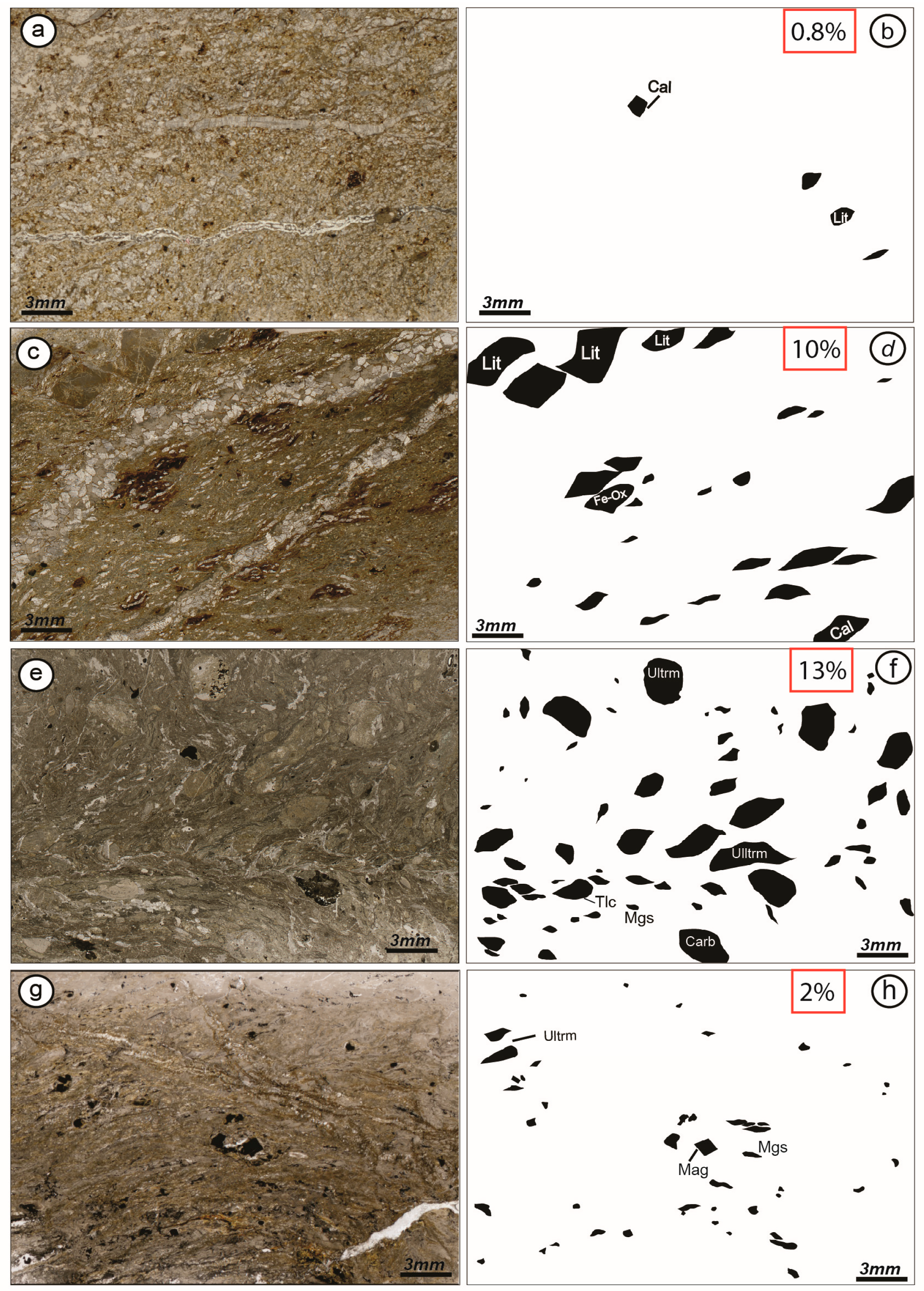
The differentiation in protomylonite-mylonite and ultramylonite has been carried out taking into account the distribution and size of porphyroclasts and their percentage areal distribution. Their semi-quantitative estimation was obtained by the free software SXM v2.5 (http://www.ImageSXM.org.uk), taking into account four scanned thin sections representative of low and high strain domains (Figure 4).
In the following section, the full range of structures are described, starting from the protomylonitic to the mylonitic and ultramylonitic rocks. In addition, a section on later brittle structures affecting the whole shear zone, is presented, in order to better constrain the different deformation phases of the study shear zone and to frame the shear zone in the Elba Island tectonic evolution.
3.1. Protomylonites
On the SW side of the shear zone, the protomylonite is composed by metasandstone with sericitic-chloritic matrix and less amount of calcitic cement. This level is weakly foliated with rare S/C structures (Figure 3g and Figure 5a). The matrix results only partly crystallized (< 50%) and the original mineral assemblage is still recognizable, made up of Qtz + Kfs + Ms ± Cal + Bt ± Chl + Fe − Ox. The grain size did not experience a drastic reduction and syntectonic minerals with a preferred orientation are rare. The porphyroclasts are scarce and often represented by lithics with common microlithic textures. The image analysis displays porphyroclasts covering an area of about 1% (Figure 4a,b). Micas, together with elongated and stretched magnesite and quartz ribbons, are mainly located along the S-foliation (Figure 5b,c). The contact between the metasandstoneprotomylonite and the metasandstonemylonites is gradual and marked by an eastward increase in the intensity of foliation and number of porphyroclasts in the matrix.
On the NE side of the shear zone, the protomylonite is characterized by the sedimentary cover of the serpentinite composed of calcilutite with interbeddedshales. This domain is less deformed with respect to the quartzo-feldspathic protomylonite and the matrix is weakly crystallized. The clayey layers, comprised between isolated calcilutite blocks, record a relatively intermediate deformation, indicated by the occurrence of a centimeter to decimeter scale top-to-the-east S/C structures, with angle of about 45° between S and C foliations, thus indicating a scarce rotational strain with respect to the one observed in the serpentine mylonites and ultramylonites (Figure 5d). The end of the protomylonitic fabric matches the lithologic passage to the basement cover, represented by the underlying serpentine.
3.2. Mylonites
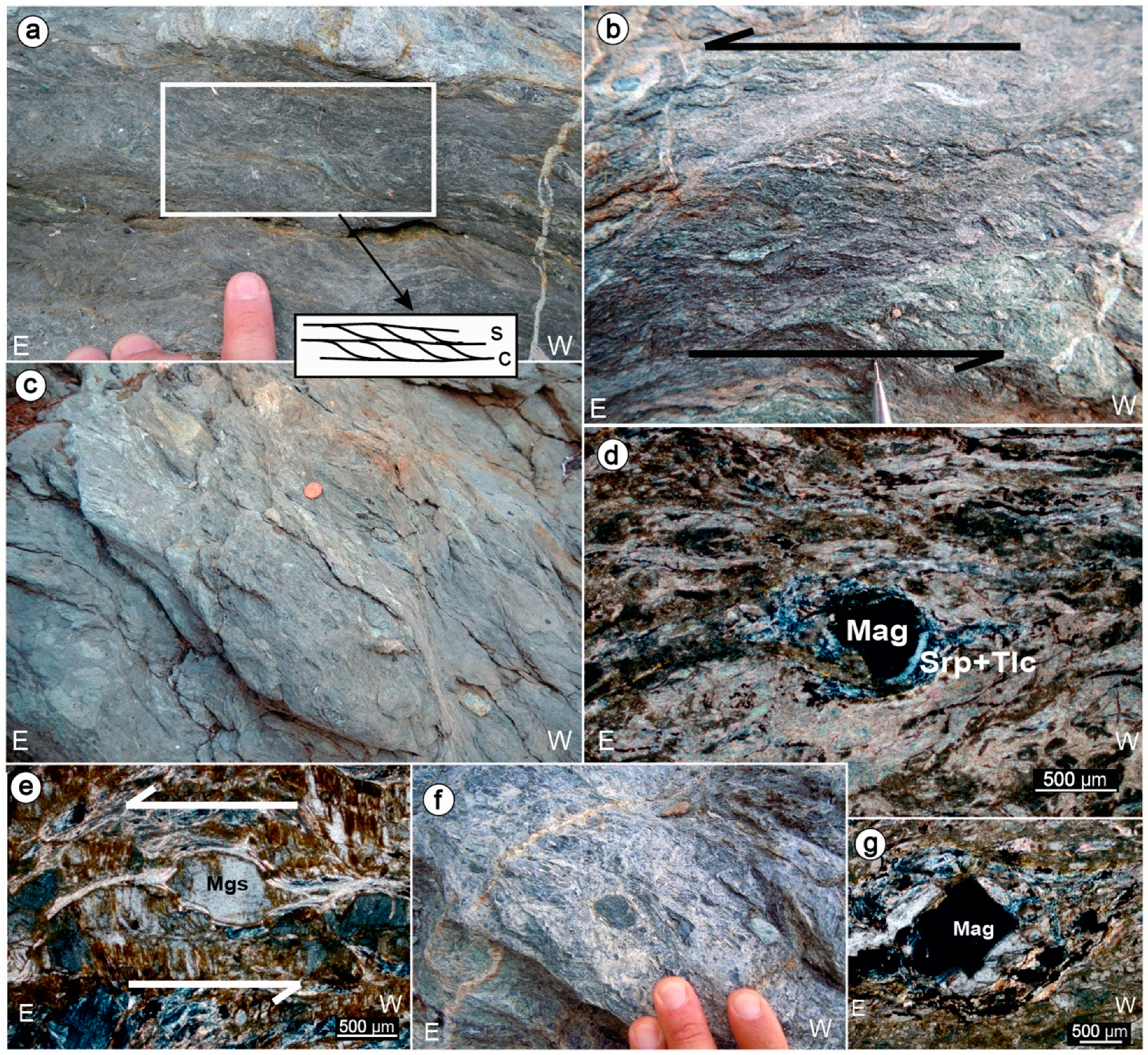
Metasandstonemylonites differ from the protomylonite by the higher proportion of dark grey crystallized matrix and a larger amount of porhyroclasts and foliation intensity. The latter is indicated by an increase in the alignment of micas and by a stretching and flattening of quartz and magnesite crystals. Foliations are here represented by S/C structures, generally making angles of less than 40° (Figure 3g). These, both in oriented thin-sections and at the outcrop scale, show a general top-to-the-ESE sense of shear (Figure 3g,h and Figure 6a).
In the matrix, dark and very fine-grained extensional shear bands (C’/C’’) are also recognizable (Figure 6a). Commonly, the porphyroclasts contained in the matrix, show small size (up to 6 × 4 cm on average) and are characterized by qtz-lithics and/or carbonate and Fe-Ox clasts (Figure 6b–g). The only exception is represented by two large (ca. 1.5 × 3 m and 90 × 50 cm) ultramafic porphyroclasts (Figure 6h), including smaller (ca. 30 × 20 cm and 15 × 5 cm, respectively) carbonate clasts.
Many porhyroclasts are parallel to the foliation or, more often, they display, σ-shape features (Figure 6c,d), locally showing strain shadows prevalently filled by white micas. Such σ-shape features point to a general top-to-the-ESE sense of shear, coherently with the S/C structures, as previously described. Occasionally, porphyroclasts are also rounded or naked-θ-type wrapped by magnesite ribbons and partly crystallized. On the whole, the average area covered by porhyroclasts is about 10% (Figure 4c,d) of the total area.
Within the myloniticserpentinite domain, the intensity of the foliation increases. The S/C fabric is well developed and porphyroclasts of ultramafic and carbonate composition (Figure 7), ranging from 5 × 8 cm to 70 × 30 cm in size (Figure 7), are abundant, covering about 13% (Figure 4e,f) of the total area. Commonly, these porphyroclasts are aligned along the main foliation (Figure 7a–c). When they have experienced rotation, they show asymmetric tails and pressure shadows, forming σ-shape structures (Figure 7b–e). With the increasing of rotation, ∂-type clasts are also generated (Figure 7f). Again, the asymmetry of porphyroclasts displays a top-to-the-east sense of shear.
Where the mylonitic serpentine passes into the ultramylonite domain, the contact is gradational and the strain intensity rises up. This is marked by an increase in the intensity of foliation, definition of S/C fabric, and a gradual decrease in the presence of porphyroclasts and their size.
3.3. Ultramylonite
Ultramylonitic serpentinites are characterized by dark-green to black crystallized matrix (<90%) and intense grain-size reduction (Figure 8a–c). These rocks show a strong planar fabric and a drastic reduction of the amount and size of the porphyroclasts. These are mainly represented by ultramafic, carbonate and magnesite clasts, with size up to 5 × 2 cm. Clasts are dispersed within a highly foliated matrix (Figure 8b–g). By the image analysis, porphyroblasts occupy an area of about 2% (Figure 4g,h), having a σ and δ-shape with pressure shadows filled by serpentine and talc. Locally, naked θ-shape porphyroclasts, typical of ultramylonites, can occur, testifying an increase in rotation, a shearing thinning and/or a complete crystallization of the porphyroclast tails. The mylonitic foliation is well preserved and it is almost parallel to the SW dipping C-plane (Figure 8a–c). This latter, coupled with the attitude of the S-planes, generates small angles (<25°), indicating a main top-to-the-SE sense of shear (Figure 3g–h), in agreement with the asymmetric shape of the porhyroclasts and the geometry of their asymmetric pressure shadow tails (Figure 8d,e,g).
3.4. Petrographic Features of the Mylonitic and Ultramylonitic Serpentine
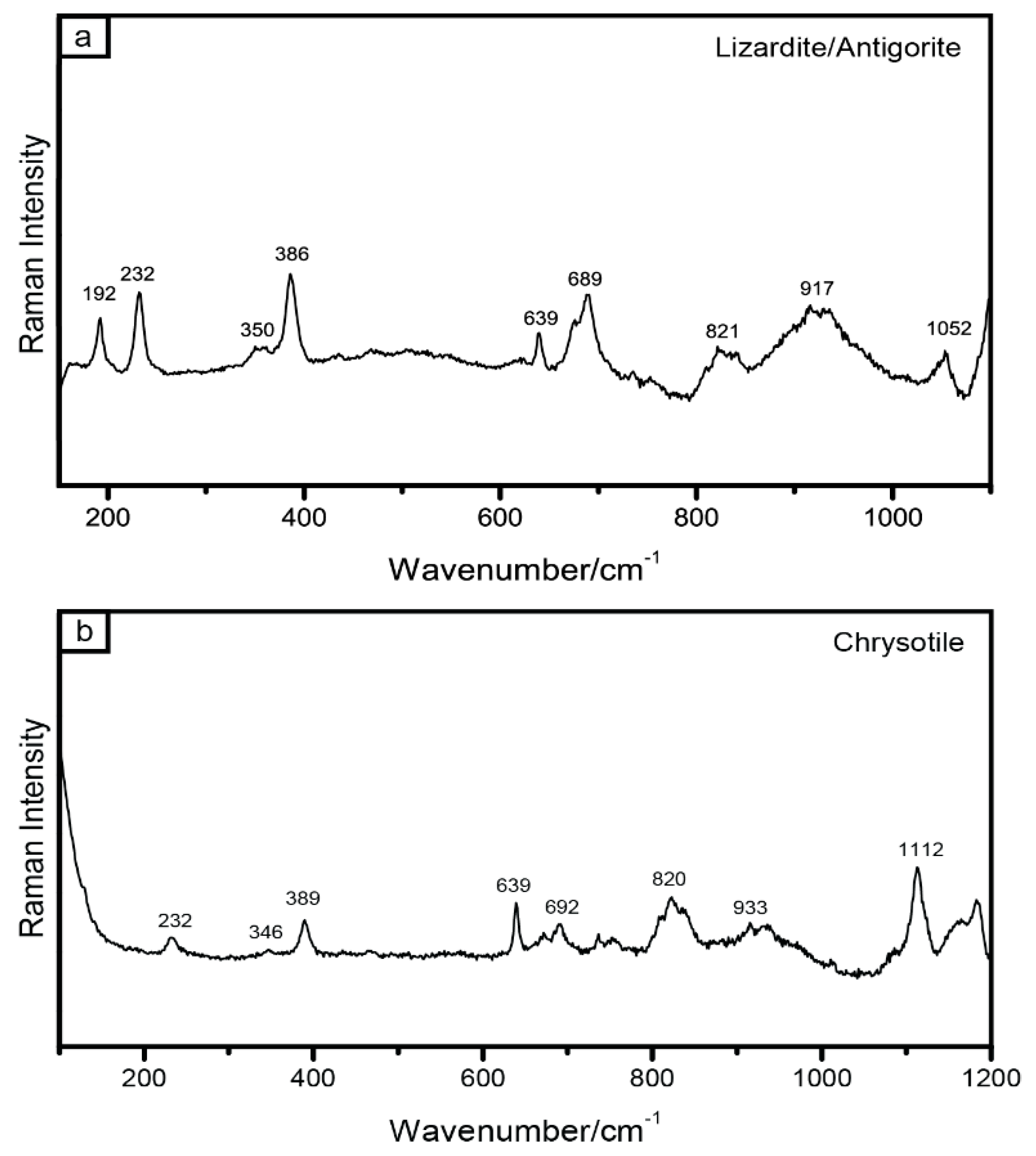
Since the serpentinite level played an important role in controlling the deformation along the shear zone, to deepen the knowledge of their mineralogical composition and microstructures, key-samples have been analyzed by SEM/EDS technique and Raman spectroscopy. The SEM/EDS operating conditions were of 15 Kv and 15 nA (Table 2), while the Raman measurements were performed using a Labram Micro-Raman spectrometer by Horiba, equipped with a He-Ne laser source at 632.8 nm (nominal output power 18 mW). The spectral region from 150 to 1100 cm−1 was investigated since these include the lattice vibration modes of the serpentine species [65]. The detected bands show low temperature serpentine minerals, such as lizardite [66], locally mixed with antigorite and in minor amount, chrysotile (Figure 9), often present with chlorite in late veins. The peaks around 800 testify the presence of olivine mesh texture. Spectra were likened to those obtained in [65,67,68,69], with comparable results.
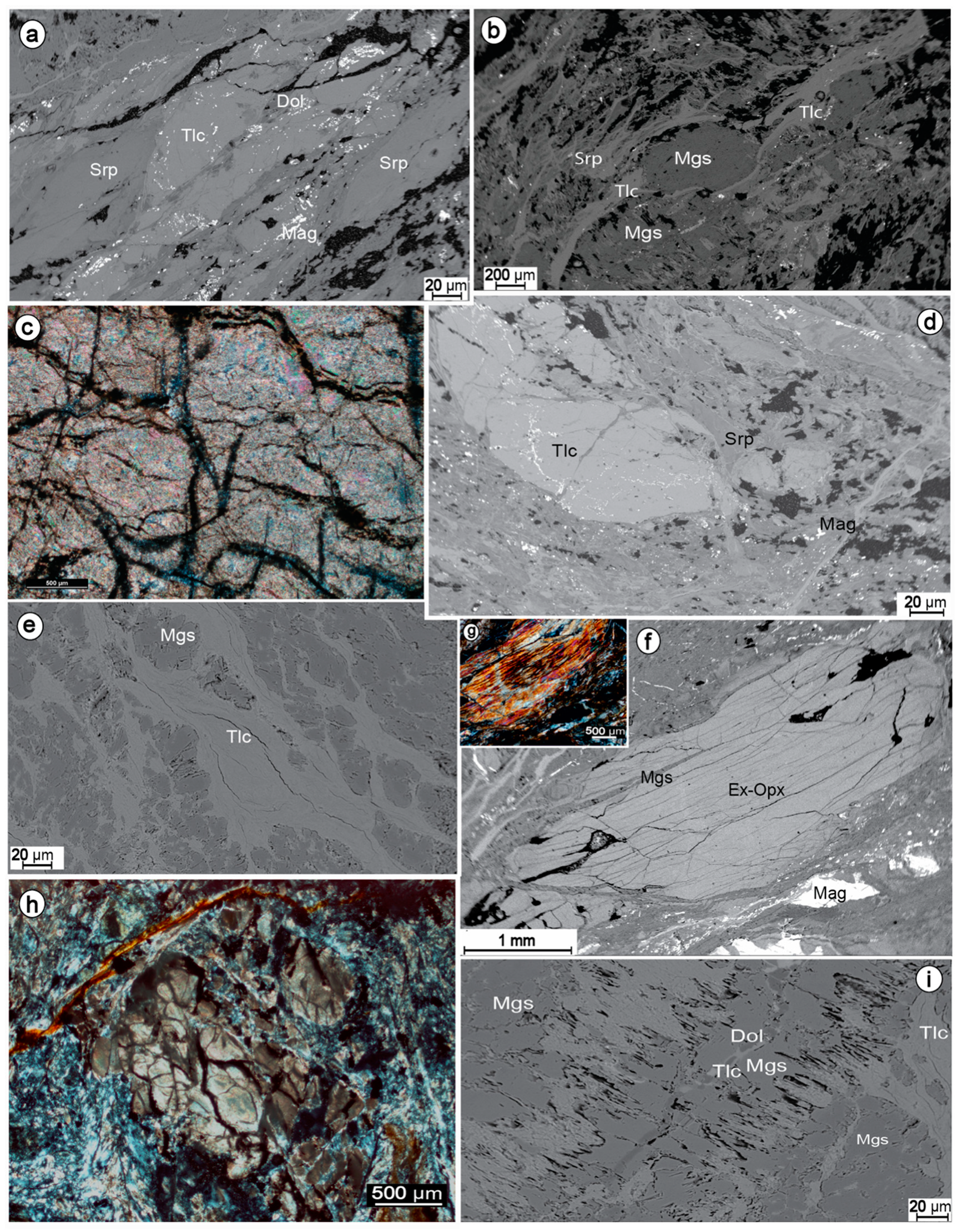
The mineralogical paragenesis, characterizing the matrix, is composed by talc-serpentine minerals-chlorite-magnesite-calcite-pyroxene-spinel-oxides and small amount of dolomite and quartz. On the whole, this mineral assemblage points to a sub-green-schistsfacies [4]. Porphyroclasts are mainly represented by lizardite-rich serpentinite fragments, talc, magnesite and calcite (Figure 10a,b). Often, talc porphyroclasts contain chrysotile vein textures (Figure 10c). There are no textures indicating a prograde alteration of lizardite to antigorite.
Crystal habits of relict orthopyroxene and olivine (Figure 10f–h), suggesting a harzburgite composition of the ultramafic protolith, are sometimes preserved, although no pure composition has been detected. However, the original orthopyroxene, is indicated by the presence of bastite (serpentine + fine-grained carbonate) and by the texture and striations disposed along the cleavage planes (Figure 10f,g). Bastite lamellae are generally colorless and with a lamellar extinction pattern. Sometimes relic pyroxene is dissected by carbonate veins (Figure 10f). Serpentinized olivine although sometimes replaced by talc, is indicated by the presence of mesh and hourglass texture with variable internal configuration, that may enclose relicts of olivine crystals, evident under optical microscope (Figure 10h). The great majority of these pseudomorphic textures are prevalently composed by micro-crystalline lizardite lamellae and minor chrysotile and antigorite, suggesting that serpentine mainly crystallized at the boundary Opx-Ol, and mostly at the expense of olivine.
Magnesite is abundant, occurring as porphyroclast wrapped by talc and serpentine (Figure 10b), and as fine aggregates in the matrix. Often magnesite is encountered as monomineralic and cryptocrystalline veinlets, with serrated or sharp contacts in the enclosing serpentinite and talc (Figure 10i). The presence of magnesite, both in the matrix and as porphyroclasts, suggests that the alteration of the protolith to foliated serpentinite predates the mylonitic event.
Magnetite, and subordinately magnesium-chromite, occurs as prismatic, sometimes brecciated and rarely elliptical. In some cases, the oxide strain shadows are characterized by talc and serpentine. During serpentinization, magnetite can precipitate during the alteration and oxidation of olivine and orthopyroxene [70,71]. In this case, magnetite forms fine clusters of tiny opaque crystals, surrounding the altered primary minerals, concentrating at the mesh rims or resulting dispersed within the serpentinite texture and deformation zone. (Figure 10h).
Within the highly deformed rock, the mylonitic and phyllonitic fabric is underlined by the presence of lizardite, chrysotile, talc, Mg-chlorite (penninite, clynochlore, Table 2) and carbonate clasts. A strongly oriented pervasive foliation, characterized by lizardite and talc (Figure 10b,d,e), is locally outlined by oxide alignment (Figure 10a), determined by the spinel Mg-chromite and magnetite (Table 2). Often, both talc and lizardite wrap porhyroclasts composed of magnesite and serpentinite fragments (Figure 10a,b,d) and occur in their strain shadows, indicating a syntectonic crystallization, coeval with the grain-size reduction, in the phyllonitic levels.
3.5. Brittle Structures
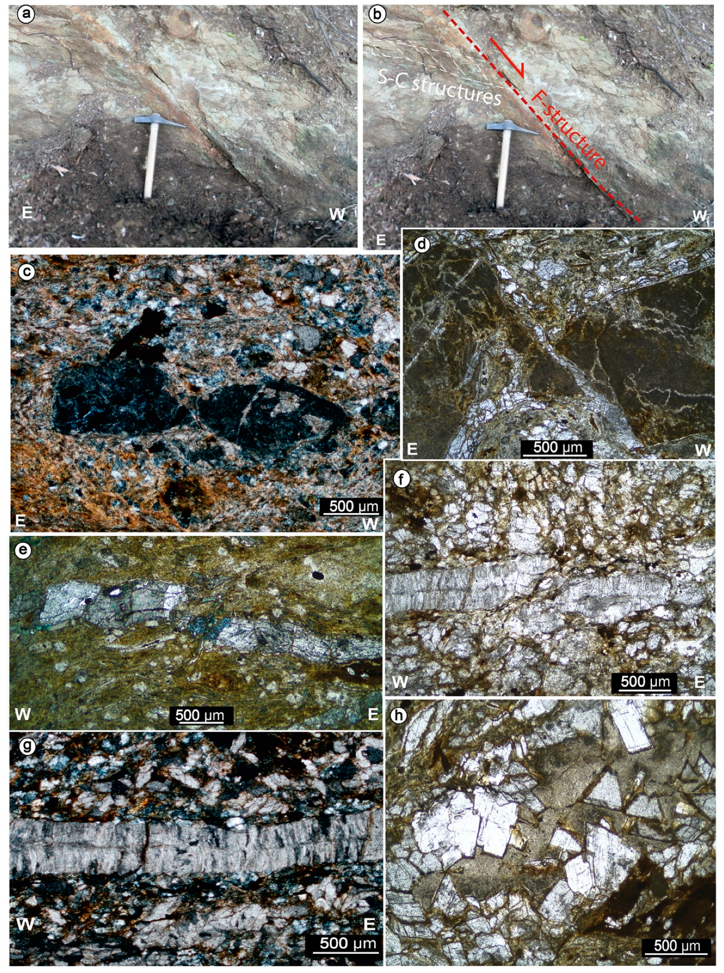
The rocks involved in the shear zone are also affected by later west dipping faults cross-cutting the previously formed S/C structures (Figure 11a,b and Figure 12a,b) and porphyroclasts (Figure 12c,d). Often these faults show shear veins on their slip surfaces with calcite mineralization (Figure 12b). Their average dip-direction is N220, with a plunge of about 50° (Figure 3g,h). These structures are also recognized at the microscale, determining the slicing of porhyroclasts (Figure 11c,d and Figure 12e–g). Locally, these grain-scale faults are also subsequent to carbonate extensional veins (Figure 11e,f). The later brittle event is also testified by occurrence of centimeter to millimeter thick E–W trending extensional fibrous antitaxial calcite and magnesite veins (Figure 11e–g and Figure 12h) and by Fe-Oxides and hydroxydes veins cross-cutting porphyroclasts. These veins become more abundant toward the domain where the continental metasandstone crops out. In most cases, the veins follow the foliation defined by the C-planes. Within the metasandstone, fibrous magnesite veins also occur, cross-cutting the main foliation. Locally, also magnesite blocky veins are found, showing well developed magnesite crystal faces and cemented by a microcrystalline calcite (Figure 11h).
In addition, the bulk of the carbonate beds belonging to the oceanic sediments are affected by calcite veins with thickness up to about 5 cm (Figure 12i). Often, these veins are characterized by small regular clasts, accounting for a contribute of the hydraulic pressure during the fracturing process. Locally, these veins also cross-cut the west-dipping brittle structures.
4. Discussion
This section discusses the deformation of the two main lithotypes controlling the evolution of the Capo Castello shear zone: the serpentinite and the quartzo-feldspathic sedimentary rocks and the implications of the study shear zone in Elba geological framework.
It is well known the principal mineral phase of serpentinite, the serpentine, is characterized by different polymorphs, reflecting different elastic [72,73] and rheological properties [26,27]. To constrain the PT to which serpentinite underwent the characterization of the serpentine polymorphs is a crucial information. Commonly, lizardite and chrysotile are the dominant varieties occurring in low-grade metamorphic ophiolites [74]. In addition, experimental studies ([68] and natural sample analyses [71], show that under 300 °C and P < 4 kbar (sub-greenschist facies) the lizardite and secondarily the chrysotile are the stable polymorphs, while between 320 °C and 380 °C and at a higher pressure (4 < P < 24 kbar, blueschists facies) the lizardite is gradually replaced by antigorite that became the only serpentine variety occurring above 380 °C.
As regards the case under study, Raman spectroscopy analysis displays that the most abundant serpentine mineral, both in the matrix and in the pseudomorphic meshes, is the low-grade lizardite and in minor amount chrysotile (Figure 9). These two polymorphs commonly occur in the sub-green-schists facies [4]. However, some spectrums show a weakly mixing of lizardite and antigorite, suggesting a transition reaction from these two polymorphs. Therefore, comparing the Capo Castello serpentinite with other experimental and natural cases [26,68,74,75,76], the hypothesized PT conditions at which the study shear zone was active are T ≈ 320 °C and P < 5 kbar, thus related to the upper part of the greenschist facies (Figure 13).
Serpentine minerals are also at the base of Capo Castello shear zone deformation mechanism, because of their low frictional coefficient due to the weak interactions among OH groups and silicate layers [26,77] mostly within the lizardite and chrysotile polymorphs [78,79]. Therefore, given the easy gliding along their basal plane [80], the deformation within the Capo Castello harzburgite protolithis favored and its serpentinization can be considered an efficient mechanism to reduce rock strength, thus permitting easy slip processes. In this context, [29] demonstrate that during serpentinization, the friction coefficient is lowered from μ = 0.6 to 0.3. According to its mineralogical assemblage, the Capo Castello serpentinite developed at low temperature (T < 320 °C), in an open system that favored the infiltration of fluids, [81] demonstrated that meteoric groundwater can be the main factor in serpentinization, forming lizardite and chrysotile minerals. In addition, as documented in several fault zones [5,30,82,83,84], the intense foliation can also derive from an earlier influx of hydrous fluids, favoring reactions in the initial stage of the cataclasite formation, thus leading to softening of the ultramafic rock and triggering fluid assisted dissolution–precipitation and pressure–solution processes (Figure 10a,d).
The high strain domain along the shear zone (Figure 10e) is also a consequence of the presence of talc and minor talc-carbonates, distributed along the serpentinite foliation [83]. Summing up, and taking into account the textural and petrographic observation, different metamorphic reactions, leading to the formation of low strength mineral phases, can be reasonably considered in the following order [85]:
3Fe2SiO4 + 2H2O = 2Fe3O4 + 3SiO2 + 2H
3Mg2SiO4 + SiO2 + 2H2O = 2Mg3Si2O5(OH)4
These first reactions lead to the serpentinization of olivine, as suggested by the pseudomorphic olivine texture (Figure 10h). These reactions produce the initial weakening of the shear zone. Fayalite is oxidized in magnetite, releasing SiO2 fluids, in turn consumed in the second reaction, to form serpentine from the forsterite component. The results assemblage is serpentine (chrysotile/lizardite), magnetite and some left unreacted olivine [83], as testified by the detected mineral phases within the serpentinite samples.
The following reaction is given by [83]:
Mg3Si2O5(OH) 4 + SiO2= Mg3Si4O10(OH)2 + H2O
Serpentine, in the presence of silica-rich fluids, can then react to provide talc, a further low strength mineralogy phase. Silica-rich fluids originate from the interaction with the neighboring quartz-rich sediments, suggesting an open system within the ultramafic rock.
The system opening, then, can bring to other, even coeval, metamorphic reactions, here referred to as (4) [86]. Magnesite, being present both along the foliation and within later veins (Figure 11e,h), can be considered as developing from the initial-to-mature stages of shearing, based on the following reaction:
4Mg2SiO4 +2H2O + 5CO2= Mg3Si4O10(OH)2 + 5MgCO3
This is enhanced by the interaction with CO2 rich fluids, coming from atmosphere and the surrounding carbonate rocks [87,88], i.e., the ophiolitic sedimentary cover, enhancing the alteration processes of the ultramafic protolith [89,90].
Furthermore, magnesite, can result from the reaction of tremolite, that is normally present in ophiolite. In our study area, however, this amphibole was never detected, thus suggesting its total involvement in the following reaction as (5) [91], producing talc, too:
Ca2Mg5Si8O22(OH)2 + 4CO2= Mg3Si4O10(OH)2 + 2CaMg(CO3) +4SiO2
It can be concluded that the strain localization and partitioning, is mainly controlled by the occurrence of infiltrated fluids when serpentine is already formed, thus influencing the mechanical behavior of the fault rocks, causing a strain softening process by syntectonic metamorphic reactions and formation of phyllosilicate networks. This process is therefore envisaged to modify low to high strain zones [86], since dissolution–precipitation processes are efficient even in low strain domains, as demonstrated in several upper crustal fault zones [92,93]. As already described, in the quartzo-feldspathic rocks, the low strain domain is represented by protomylonitic fabrics. It shows a partly crystallized matrix (<50%), a slight grain size reduction (Figure 5a,e) and rare newly forming minerals, with a weak preferred orientation. The foliation is well expressed and porphyroclasts are scarce. Differently, the higher strain domain, characterized by a mylonitic fabrics, displays an increased proportion of crystallized matrix, a higher amount of porhyroclasts and foliation intensity, diffuse top-to-the-east S/C structures, alignment of micas, and stretching and flattening of quartz and magnesite crystals (Figure 6). The occurrence of magnesite testifies the presence of syntectonic magnesium-bearing solutions within the quartzo-feldspathic rocks. Fluids, in fact, became Ca− and Mg− enriched, passing firstly through the ophiolitecarbonatic cover and then through the serpentinite levels, structurally located at the top of the quartzo-feldspathic rocks. At the 200–300 °C temperature interval the presence of fluids activates pressure–solution processes [88], becoming the dominant deformation mechanism. As a consequence, the production of relative lower strength mineral phases, as biotite and white mica and their segregation in particular layers, led to a softening reaction process and volume reduction [19].On the whole, along the Capo Castello shear zone, the serpentinite domain results the most deformed with respect to the metasandstone; this indicates that during the shear zone activity the crystallization and fluid flow were strongly localized within the serpentinite rocks.
As regards the frame of the Elba island regional geology, the structural and petrographic features of the Capo Castello shear zone can be compared with the Zuccale normal fault (Figure 1), an extensional regional structure affecting Elba Island and locally juxtaposing ophiolite onto quartzitic rocks [30,55,56,57,58,84]. Both shear zones, in fact, are characterized by S/C and C/C’ type shear structures, having a general consistent top-to-the-east sense of shear (Figure 14).
According to the Zuccale fault zoning, proposed by [56], their highly foliated levels (L2–L3) with serpentine-tremolite-talc-chlorite schists and chlorite phyllonite record the same deformational mechanisms of the Capo Castello serpentinite level. The main difference between the two structures is that, the Zuccale fault is characterized by a concentrated level of low strength mineral phases, whereas the latter is more widely distributed in the Capo Castello shear zone, probably a consequence of the original composition of the involved ultramaphics and/or to a minor degree of flattening. Another difference between the Zuccale and Capo Castello shear zone can be recognized in the origin of silica-rich fluids. These are in fact related to a magmatic origin at Zuccale, due to the proximity with the Porto Azzurro Pluton. Differently, the Capo Castello area is far from any magma source [46] and therefore the origin of silica rich fluids should be related to fluid circulation from nearest quartzo-feldspathic rocks. Finally, from a tectonic point of view, both structures determined a tectonic omission in the original stacked pile, although at different stages of evolution (Figure 15). By this, the Capo Castello shear zone, located in the hanging wall of the Zuccale fault, can be considered as a part of the deformation associated to an older, exhumed, regional detachment, representative of the initial stage of deformation, now visible at Zuccale in its mature stage. Regarding kinematics, at Capo Castello shear zone, it was observed that the micro and meso-structures generally point to a top-to-the-east sense of shear (Figure 14), while the main shear zone attitude is dipping to the west (Figure 2), as all the later brittle structures cross cutting the S/C pairs and the asymmetric porphyroclasts. This feature suggests a passive rotation of the fault hangingwall as a consequence of gravitational processes occurred during the lateral crustal segmentation that generated megaboudin structures, as already documented in other part of the Tuscany ([41,49,50]). In this context, the kinematic indicators of the study shear zone were also rotated and the present top-to-ESE kinematic indication (Figure 3) is reasonably influenced by this latter process.
Finally, even if no dating is available in this area, the activity of the Capo Castello shear zone can be encompassed between 19.8 ± 1.4 Ma ([33], age of HP event) and late Miocene–Early Pliocene (age of Zuccale activity, [59]). In this view, the west dipping F-structures (i.e., the latest brittle deformation), accommodated the passive rotation of the hangingwall.
5. Conclusions
The study of the geometry, kinematics, textural and mineral chemistry of the Capo Castello shear zone allowed to draw the following conclusions:
Along the shear zone the heterogeneous strain effects are prevalently influenced by lithology. Within the quartzofeldspathic rocks the low strain domains are expressed by a protomylonitic fabric, generally characterized by a poorly crystallized matrix and a weak grain size reduction and foliation. Within the higher strain domain, the metasandostones show a mylonitic fabric with a dark grey crystallized matrix and a higher amount of porhyroclasts and foliation intensity, represented by a top-to-the-east S/C structure, locally accompanied by C’/C’’ shear bands. Apart from the ophiolitic sedimentary cover showing a weak protomylonitic fabric, the serpentinite level records a more intense deformation. In fact, the low strain domains are characterized by a mylonitic fabric, while the higher strain domains by an ultramylonitic one, both of them displaying an intense foliation marked by S/C structures. These two domains show an alternation along the shear zone without a clear strain gradient from the edge to the center of the structure. The passage from the mylonites zone to the ultramylonites is underlined by increasing the proportion of crystallized matrix, of the grain-size reduction and of the number and size of the porphyroclasts. Within the ophiolitic rocks, the partitioning of the strain is expressed as the development of the mylonitic fabric in the low strain domains, and of the ultramylonitic fabric in the high strain ones.
The serpentinite level, due to the peculiar mineralogy of the serpentine minerals, acts as a lubricant along the shear zone, accommodating most of the deformation. The presence of the infiltrated fluid influences the mechanical behavior of the serpentinite, causing strain softening processes by sintectonic metamorphic reactions and dissolution–precipitation processes leading to the final formation of a low strength phyllosilicate networks dominated by talc.
As a maximum, deformation ceased at T ≅ 320 °C and P < 5 kbar (upper greenschistsfacies) as defined by the stability field of lizardite + chrysotile, the dominant serpentine polymorph along the Capo Castello shear zone, and by the antigorite mixing testifying the previous transition to lizardite.
In the frame of the extensional tectonics continuously characterizing the inner northern Apennines since the Miocene, the study shear zone is considered an older, exhumed analogue of the Zuccale low-angle normal fault. According to this interpretation, this structure is ascribed to an extensional detachment acted in the time interval between the high-pressure event (19.8 ± 1.4 Ma) and the activity of the Zuccale normal fault (Late Miocene–Early Pliocene). The main novelty of this work is to have recognized a shear zone, being part of an older, exhumed structure comparable to the low-angle Zuccale regional fault. This implies that the extensional tectonics continuously developed through time, joined with regional uplift and exhumation.
Funding
The research leading to these results has received funding from the European Community’s Seventh Framework Program under grant agreement No. 608553 (Project IMAGE).
Acknowledgments
Two anonymous reviewers, by their constructive criticism and suggestions, helped me to improve the original manuscript.
Conflicts of Interest
The author declares no conflict of interest.
References
- Pennacchioni, G.; Mancktelow, N.S. Nucleation and initial growth of a shear zone network within compositionally and structurally heterogeneous granitoids under amphibolite facies conditions. J. Struct. Geol. 2007, 29, 1757–1780. [Google Scholar] [CrossRef]
- Van der Zee, W.; Wibberley, C.A.; Urai, J.L. The influence of layering and pre-existing joints on the development of internal structure in normal fault zones: The Lodève basin, France. Geol. Soc. Lond. Spec. Publ. 2008, 299, 57–74. [Google Scholar] [CrossRef]
- Regenauer-Lieb, K.; Weinberg, R.; Rosenbaum, G. The effect of energy feedbacks on continental strength. Nature 2006, 442, 67–70. [Google Scholar] [CrossRef] [PubMed]
- Barnes, I.; O’Neil, J.R. The relationship between fluids in some fresh alpine-type ultramafics and possible modern serpentinization, western United States. Geol. Soc. Am. Bull. 1969, 80, 1947–1960. [Google Scholar] [CrossRef]
- Evans, J.P.; Chester, F.M. Fluid-rock interaction in faults of the San Andreas system: Inferences from San Gabriel fault rock geochemistry and microstructures. J. Geophys. Res. Solid Earth 1995, 100, 13007–13020. [Google Scholar] [CrossRef]
- White, S.H.; Burrows, S.E.; Carreras, J.; Shaw, N.D.; Humphreys, F.J. On mylonites in ductile shear zones. J. Struct. Geol. 1980, 2, 175–187. [Google Scholar] [CrossRef]
- Platt, J.P.; Behr, W.M. Grain size evolution in ductile shear zones: Implications for strain localization and the strength of the lithosphere. J. Struct. Geol. 2011, 33, 537–550. [Google Scholar] [CrossRef]
- Menegon, L.; Stünitz, H.; Nasipuri, P. Partitioning of metamorphism and deformation at the nappe scale and implications for nappe-stacking mechanisms: The example of the Kalaknappe complex (north-Norwegian Caledonides). In Proceedings of the EGU General Assembly Conference Abstracts, Vienna, Austria, 22–27 April 2012. [Google Scholar]
- Ruiz-Agudo, E.; Putnis, C.V.; Putnis, A. Coupled dissolution and precipitation at mineral–fluid interfaces. Chem. Geol. 2014, 383, 132–146. [Google Scholar] [CrossRef]
- Gratier, J.P.; Thouvenot, F.; Jenatton, L.; Tourette, A.; Doan, M.L.; Renard, F. Geological control of the partitioning between seismic and aseismic sliding behaviours in active faults: Evidence from the Western Alps, France. Tectonophys. 2013, 600, 226–242. [Google Scholar] [CrossRef]
- Silver, C.R.; Murphy, M.A.; Taylor, M.H.; Gosse, J.; Baltz, T. Neotectonics of the western Nepal fault system: Implications for Himalayan strain partitioning. Tectonics 2015, 34, 2494–2513. [Google Scholar] [CrossRef] [Green Version]
- Liu, Q.; van der Hilst, R.D.; Li, Y.; Yao, H.; Chen, J.; Guo, B.; Qi, S.; Wang, J.; Huang, H.; Li, S. Eastward expansion of the Tibetan Plateau by crustal flow and strain partitioning across faults. Nat. Geosci. 2014, 7, 361–365. [Google Scholar] [CrossRef]
- Leever, K.A.; Gabrielsen, R.H.; Sokoutis, D.; Willingshofer, E. The effect of convergence angle on the kinematic evolution of strain partitioning in transpressional brittle wedges: Insight from analog modeling and high-resolution digital image analysis. Tectonics 2011, 30, TC2013. [Google Scholar] [CrossRef]
- Lee, P.E.; Jessup, M.J.; Shaw, C.A.; Hicks III, G.L.; Allen, J.L. Strain partitioning in the mid-crust of a transpressional shear zone system: Insights from the Homestake and Slide Lake shear zones, central Colorado. J. Struct. Geol. 2012, 39, 237–252. [Google Scholar] [CrossRef]
- Zhang, B.; Zhang, J.; Zhong, D. Structure, kinematics and ages of transpression during strain-partitioning in the Chongshan shear zone, western Yunnan, China. J. Struct. Geol. 2010, 32, 445–463. [Google Scholar] [CrossRef]
- Holdsworth, R.E.; Tavarnelli, E.; Clegg, P.; Pinheiro, R.V.L.; Jones, R.R.; McCaffrey, K.J.W. Domain deformation patterns and strain partitioning during transpression: An example from the Southern Uplands terrane, Scotland. J. Geol. Soc. 2002, 159, 401–415. [Google Scholar] [CrossRef]
- Beltrando, M.; Rubatto, D.; Manatschal, G. From passive margins to orogens: The link between ocean-continent transition zones and (ultra) high-pressure metamorphism. Geology 2010, 38, 559–562. [Google Scholar] [CrossRef]
- Molli, G.; Tribuzio, R.; Marquer, D. Deformation and metamorphism at the eastern border of the Tenda Massif (NE Corsica): A record of subduction and exhumation of continental crust. J. Struct. Geol. 2006, 28, 1748–1766. [Google Scholar] [CrossRef]
- Wintsch, R.P.; Yi, K. Dissolution and replacement creep: A significant deformation mechanism in mid-crustal rocks. J. Struct. Geol. 2002, 24, 1179–1193. [Google Scholar] [CrossRef]
- Guillot, S.; Schwartz, S.; Reynard, B.; Agard, P.; Prigent, C. Tectonic significance of serpentinites. Tectonophysics 2015, 646, 1–19. [Google Scholar] [CrossRef]
- Chernak, L.J.; Hirth, G. Deformation of antigorite serpentinite at high temperature and pressure. Earth Planet. Sci. Lett. 2010, 296, 23–33. [Google Scholar] [CrossRef]
- Schroeder, T.; John, B.E. Strain localization on an oceanic detachment fault system, Atlantis Massif, 30N, Mid-Atlantic Ridge. Geochem. Geophys. Geosyst. 2004, 5, Q11007. [Google Scholar] [CrossRef] [Green Version]
- Passchier, C.W.; Simpson, C. Porphyroclast systems as kinematic indicators. J. Struct. Geol. 1986, 8, 831–843. [Google Scholar] [CrossRef]
- Mancktelow, N.S. How ductile are ductile shear zones? Geology 2006, 34, 345–348. [Google Scholar] [CrossRef]
- Raleigh, C.B.; Paterson, M.S. Experimental deformation of serpentinite and its tectonic implications. J. Geophys. Res. 1965, 70, 3965–3985. [Google Scholar] [CrossRef]
- Amiguet, E.; Van De Moortèle, B.; Cordier, P.; Hilairet, N.; Reynard, B. Deformation mechanisms and rheology of serpentines in experiments and in nature. J. Geophys. Res. Solid Earth 2014, 119, 4640–4655. [Google Scholar] [CrossRef]
- Hirauchi, K.I.; Katayama, I. Rheological contrast between serpentine species and implications for slab–mantle wedge decoupling. Tectonophysics 2013, 608, 545–551. [Google Scholar] [CrossRef]
- Morrow, C.A.; Moore, D.E.; Lockner, D.A. The effect of mineral bond strength and adsorbed water on fault gouge frictional strength. Geophys. Res. Lett. 2000, 27, 815–818. [Google Scholar] [CrossRef] [Green Version]
- Escartin, J.; Hirth, G.; Evans, B. Nondilatant brittle deformation of serpentinites: Implications for Mohr-Coulomb theory and the strength of faults. J. Geophys. Res. Solid Earth 1997, 102, 2897–2913. [Google Scholar] [CrossRef]
- Collettini, C.; Viti, C.; Smith, S.A.F.; Holdsworth, R.E. Development of interconnected talc networks and weakening of continental low-angle normal faults. Geology 2009, 37, 567–570. [Google Scholar] [CrossRef]
- Viti, C.; Hirose, T. Dehydration reactions and micro/nanostructures in experimentally-deformed serpentinites. Contrib. Mineral. Petrol. 2009, 157, 327–338. [Google Scholar] [CrossRef]
- Bianco, C.; Brogi, A.; Caggianelli, A.; Giorgetti, G.; Liotta, D.; Meccheri, M. HP-LT metamorphism in Elba Island: Implications for the geodynamic evolution of the inner Northern Apennines (Italy). J. Geodyn. 2015, 91, 13–25. [Google Scholar] [CrossRef]
- Bianco, C.; Godard, G.; Halton, A.; Brogi, A.; Liotta, D.; Caggianelli, A. The lawsonite-glaucophaneblueschists of Elba Island (Italy). Lithos 2019, 348–349, 105198. [Google Scholar] [CrossRef]
- Ramsay, J.G.; Graham, R.H. Strain variation in shear belts. Can. J. Earth Sci. 1970, 7, 786–813. [Google Scholar] [CrossRef]
- Sibson, R.H. Transient discontinuities in ductile shear zones. J. Struct. Geol. 1980, 2, 165–171. [Google Scholar] [CrossRef]
- Vitale, S.; Mazzoli, S. Heterogeneous shear zone evolution: The role of shear strain hardening/softening. J. Struct. Geol. 2008, 30, 1383–1395. [Google Scholar] [CrossRef]
- Bonini, M.; Cerrina Feroni, A.; Martinelli, P.; Moratti, G.; Valleri, G.; Certini, L. The intramessinian angular unconformity within the Radicondoli syncline (Siena, Tuscany, Italy): Structural and biostratigraphical preliminary data. Mem. Soc. Geol. Ital. 1994, 48, 501–507. [Google Scholar]
- Bonini, M.; Moratti, G. Evoluzione tettonica del bacino neogenico di Radiocondoli-Volterra (Toscana meridionale). Boll. Soc. Geol. Ital. 1995, 114, 549–573. [Google Scholar]
- Moratti, G.; Bonini, M. Structural development of the NeogeneRadicondoli–Volterra and adjoining hinterland basins in Western Tuscany (Northern Apennines, Italy). Geol. J. 1998, 33, 223–241. [Google Scholar] [CrossRef]
- Sani, F.; Bonini, M.; Cerina Feroni, A.; Mazzarini, F.; Moratti, G.; Musumeci, G.; Corti, G. Iatta, F.; Ellero, A. Messinian-Early Pliocene crustal shortening along the Tyrrhenian margin of Tuscany, Italy. Boll. Soc. Geol. Ital. 2009, 128, 593–604. [Google Scholar]
- Musumeci, G.; Vaselli, L. Neogene deformation and granite emplacement in the metamorphic units of northern Apennines (Italy): Insights from mylonitic marbles in the Porto Azzurro pluton contact aureole (Elba Island). Geosphere 2012, 8, 470–490. [Google Scholar] [CrossRef] [Green Version]
- Bonini, M.; Moratti, G.; Sani, F.; Balestrieri, M.L. Compression-to-extension record in the Late Pliocene-Pleistocene Upper Valdarno Basin (Northern Apennines, Italy): Structural and thermochronological constraints. Ital. J. Geosci. 2013, 132, 54–80. [Google Scholar] [CrossRef]
- Brogi, A. Contractional structures as relicts of the Northern Apennines collisional stage recorded in the Tuscan nappe of the Mt. Amiata geothermal area (Italy). Boll. Soc. Geol. Ital. 2005, 4, 53–64. [Google Scholar]
- Brogi, A.; Lazzarotto, A.; Liotta, D.; Ranalli, G.; CROP18 Working Group. Crustal structures in the geothermal areas of southern Tuscany (Italy): Insights from the CROP 18 deep seismic reflection lines. J. Volcanol. Geotherm. Res. 2005, 148, 60–80. [Google Scholar] [CrossRef]
- Brogi, A.; Fidolini, F.; Liotta, D. Tectonic and sedimentary evolution of the Upper Valdarno Basin: New insights from the lacustrine S. Barbara Basin. Ital. J. Geosci. 2013, 132, 81–97. [Google Scholar]
- Liotta, D.; Brogi, A.; Meccheri, M.; Dini, A.; Bianco, C.; Ruggieri, G. Coexistence of low-angle normal and high-angle strike-to oblique-slip faults during Late Miocene mineralization in eastern Elba Island (Italy). Tectonophysics 2015, 660, 17–34. [Google Scholar] [CrossRef]
- Brogi, A.; Liotta, D. Highly extended terrains, lateral segmentation of the substratum, and basin development: The middle-late Miocene Radicondoli Basin (inner northern Apennines, Italy). Tectonics 2008, 27, 1–20. [Google Scholar] [CrossRef]
- Boccaletti, M.; Elter, P.; Guazzone, G.P. Plate tectonic models for the development of the western Alps and Northern Apennines. Nature 1971, 234, 108–111. [Google Scholar] [CrossRef]
- Scandone, P. Origin of the Tyrrhenian Sea and Calabrian Arc. Boll. Soc. Geol. Ital. 1979, 98, 27–34. [Google Scholar]
- Molli, G. Northern Apennines-Corsica orogenic system: An updated overview. Siegesmund, S., Fügenschuh, B., Froitzheim N. (Eds.), Tectonic aspects of the Alpine–Dinaride–Carpathian system. Geol. Soc. London Spec. Publ. 2008, 298, 413–442. [Google Scholar] [CrossRef]
- Carmignani, L.; Decandia, F.A.; Disperati, L.; Fantozzi, P.L.; Lazzarotto, A.; Liotta, D.; Oggiano, G. Relationships between the Sardinia–Corsica–Provencal Domain and the Northern Apennines. Terra Nova 1995, 7, 128–137. [Google Scholar] [CrossRef]
- Barchi, M.; Beltrando, M. The Neogene-Quaternary evolution of the Northern Apennines: Crustal structure, style of deformation and seismicity. J. Virtual Explor. 2010, 36. [Google Scholar] [CrossRef]
- Rossetti, F.; Glodny, J.; Theye, T.; Maggi, M. Pressure–temperature–deformation–time of the ductile Alpine shearing in Corsica: From orogenic construction to collapse. Lithos 2015, 218, 99–116. [Google Scholar] [CrossRef]
- Serri, G.; Innocenti, F.; Manetti, P. Geochemical and petrological evidence of the subduction of delaminated Adriatic continental lithosphere in the genesis of the Neogene Quaternary magmatism of central Italy. Tectonophysics 1993, 223, 117–147. [Google Scholar] [CrossRef]
- Keller, J.V.A.; Pialli, G. Tectonics of the island of Elba: A reappraisal. Boll. Soc. Geol. Ital. 1990, 109, 413–425. [Google Scholar]
- Collettini, C.; Holdsworth, R.E. Fault zone weakening and character of slip along low-angle normal faults: Insights from the Zuccale fault, Elba, Italy. J. Geol. Soc. 2004, 161, 1039–1051. [Google Scholar] [CrossRef]
- Smith, S.A.F.; Holdsworth, R.E.; Collettini, C. Interactions between Low-Angle normal faults and plutonism in the upper crust: Insights from the Island of Elba, Italy. Bull. Geol. Soc. Am. 2011, 123, 329–346. [Google Scholar] [CrossRef]
- Westerman, D.S.; Dini, A.; Innocenti, F.; Rocchi, S. Rise and fall of a nested Christmas-tree laccolith complex, Elba Island, Italy. Geol. Soc. Lond. Spec. Publ. 2004, 234, 195–213. [Google Scholar] [CrossRef]
- Dini, A.; Innocenti, F.; Rocchi, S.; Tonarini, S.; Westerman, D.S. The magmatic evolution of the late Miocene laccolith–pluton–dyke granitic complex of Elba Island, Italy. Geol. Mag. 2002, 139, 257–279. [Google Scholar] [CrossRef]
- Maineri, C.; Benvenuti, M.; Costagliola, P.; Dini, A.; Lattanzi, P.; Ruggieri, G.; Villa, I.M. Sericitic alteration at the La Crocetta deposit (Elba Island, Italy): Interplay between magmatism, tectonics and hydrothermal activity. Miner. Depos. 2003, 38, 67–86. [Google Scholar] [CrossRef]
- Bortolotti, V.; Fazzuoli, M.; Pandeli, F.; Principi, G.; Babbini, A.; Corti, S. Geology of Central and Eastern Elba Island Italy. Ofioliti 2001, 26, 97–150. [Google Scholar]
- Duranti, S.; Palmeri, R.; Pertusati, P.C.; Ricci, C.A. Geological evolution and metamorphic petrology of the basal sequences of eastern Elba (complex II). ActaVulcanol. 1992, 2, 213–229. [Google Scholar]
- Pandeli, E.; Bortolotti, V.; Principi, G. La successione toscana epimetamorfica di Capo Castello (Cavo, Isola d’Elba nord-orientale). Atti Ticinesi Scienze Terra 1995, 38, 171–191. [Google Scholar]
- Elter, F.M.; Pandeli, E. Structural evolution of anchi-/epimetamorphic units of Central and Eastern Elba (Ortano, Acquadolce, Monticiano-Roccastrada and Grassera Units). Ofioliti 2001, 26, 219–228. [Google Scholar]
- Rinaudo, C.; Gastaldi, D.; Belluso, E. Characterization of chrysotile, antigorite and lizardite by FT-Raman spectroscopy. Can. Mineral. 2003, 41, 883–890. [Google Scholar] [CrossRef]
- Viti, C.; Mellini, M. Contrasting chemical compositions in associated lizardite and chrysotile in veins from Elba, Italy. Eur. J. Mineral. 1997, 9, 585–596. [Google Scholar] [CrossRef]
- Petriglieri, J.R.; Salvioli Mariani, E.; Mantovani, L.; Tribaudino, M.; Lottici, P.P.; Laporte-Magoni, C.; Bersani, D. Micro-Raman mapping of the polymorphs of serpentine. J. Raman Spectrosc. 2015, 46, 953–958. [Google Scholar] [CrossRef]
- Groppo, C.; Rinaudo, C.; Cairo, S.; Gastaldi, D.; Compagnoni, R. Micro-Raman spectroscopy for a quick and reliable identification of serpentine minerals from ultramafics. Eur. J. Miner. 2006, 18, 319–329. [Google Scholar] [CrossRef]
- Schwartz, S.; Guillot, S.; Reynard, B.; Lafay, R.; Debret, B.; Nicollet, C.; Lanari, P.; Auzende, A.L. Pressure–temperature estimates of the lizardite/antigorite transition in high pressure serpentinites. Lithos 2013, 178, 197–210. [Google Scholar] [CrossRef] [Green Version]
- Andréani, M.; Boullier, A.M.; Gratier, J.P. Development of schistosity by dissolution–crystallization in a Californian serpentinite gouge. J. Struct. Geol. 2005, 27, 2256–2267. [Google Scholar]
- Viti, C.; Mellini, M. Mesh textures and bastites in the Elba retrograde serpentinites. Eur. J. Mineral. 1998, 10, 1341–1359. [Google Scholar] [CrossRef] [Green Version]
- Christensen, N.I. Serpentinites, peridotites, and seismology. Int. Geol. Rev. 2004, 46, 795–816. [Google Scholar] [CrossRef]
- Boudier, F.; Baronnet, A.; Mainprice, D. Serpentine mineral replacements of natural olivine and their seismic implications: Oceanic lizardite versus subduction-related antigorite. J. Petrol. 2009, 51, 495–512. [Google Scholar] [CrossRef]
- Evans, B.W. The serpentinite multisystem revisited: Chrysotile is metastable. Int. Geol. Rev. 2004, 46, 479–506. [Google Scholar] [CrossRef]
- O’Hanley, D.S. Serpentinites, Records of Tectonic and Petrological History; Oxford University Press: New York, NY, USA, 1996; p. 277. [Google Scholar]
- Nicolas, A.; Meshi, A.; Boudier, F.; Jousselin, D.; Muceku, B. Mylonites in ophiolite of Mirdita (Albania): Oceanic detachment shear zone. Geosphere 2017, 13, 136–154. [Google Scholar] [CrossRef] [Green Version]
- Reinen, L.A.; Weeks, J.D.; Tullis, T.E. The frictional behavior of lizardite and antigorite serpentinites: Experiments, constitutive models, and implications for natural faults. Pure Appl. Geophys. 1994, 143, 317–358. [Google Scholar] [CrossRef]
- Moore, D.E.; Lockner, D.A.; Ma, S.; Summers, R.; Byerlee, J.D. Strengths of serpentinite gouges at elevated temperatures. J. Geophys. Res. Solid Earth 1997, 102, 14787–14801. [Google Scholar] [CrossRef]
- Behnsen, J.; Faulkner, D.R. The effect of mineralogy and effective normal stress on frictional strength of sheet silicates. J. Struct. Geol. 2012, 42, 49–61. [Google Scholar] [CrossRef]
- Hirauchi, K.I.; Michibayashi, K.; Ueda, H.; Katayama, I. Spatial variations in antigorite fabric across a serpentinite subduction channel: Insights from the Ohmachi Seamount, Izu-Bonin frontal arc. Earth Planet. Sci. Lett. 2010, 299, 196–206. [Google Scholar] [CrossRef] [Green Version]
- Wenner, D.B.; Taylor, H.P. Temperatures of serpentinization of ultramafic rocks based on O18/O16 fractionation between coexisting serpentine and magnetite. Contrib. Miner. Petrol. 1971, 32, 165–185. [Google Scholar] [CrossRef]
- Holdsworth, R.E.; Stewart, M.; Imber, J.; Strachan, R.A. The structure and rheological evolution of reactivated continental fault zones: A review and case study. Geol. Soc. Lond. Spec. Publ. 2001, 184, 115–137. [Google Scholar] [CrossRef]
- Moore, D.E.; Rymer, M.J. Talc-bearing serpentinite and the creeping section of the San Andreas fault. Nature 2007, 448, 795–797. [Google Scholar] [CrossRef] [PubMed]
- Collettini, C.; Niemeijer, A.; Viti, C.; Marone, C. Fault zone fabric and fault weakness. Nature 2009, 462, 907–910. [Google Scholar] [CrossRef] [PubMed]
- Bucher, K.; Grapes, R. Petrogenesis of Metamorphic Rocks: Metamorphism of Ultramafic Rocks; Springer: Berlin/Heidelberg, Germany, 2011; pp. 191–338. [Google Scholar]
- Kelemen, P.B.; Hirth, G. Reaction-driven cracking during retrograde metamorphism: Olivine hydration and carbonation. Earth Planet. Sci. Lett. 2012, 345, 81–89. [Google Scholar] [CrossRef]
- Klein, F.; Garrido, C.J. Thermodynamic constraints on mineral carbonation of serpentinizedperidotite. Lithos 2011, 126, 147–160. [Google Scholar] [CrossRef]
- Quesnel, B.; Gautier, P.; Boulvais, P.; Cathelineau, M.; Maurizot, P.; Cluzel, D.; Ulrich, M.; Guillot, S.; Lesimple, S.; Couteau, C. Syn-tectonic, meteoric water-derived carbonation of the New Caledonia peridotitenappe. Geology 2013, 41, 1063–1066. [Google Scholar] [CrossRef]
- Abu-Jaber, N.S.; Kimberley, M.M. Origin of ultramafic-hosted vein magnesite deposits. Ore Geol. Rev. 1992, 7, 155–191. [Google Scholar] [CrossRef]
- Boschi, C.; Dini, A.; Dallai, L.; Ruggieri, G.; Gianelli, G. Enhanced CO2-mineral sequestration by cyclic hydraulic fracturing and Si-rich fluid infiltration into serpentinites at Malentrata (Tuscany, Italy). Chem. Geol. 2009, 265, 209–226. [Google Scholar] [CrossRef]
- El-Sharkawy, M.F. Talc mineralization of ultramafic affinity in the Eastern Desert of Egypt. Miner. Depos. 2000, 35, 346–363. [Google Scholar] [CrossRef]
- Mancktelow, N.S.; Pennacchioni, G. The control of precursor brittle fracture and fluid—Rock interaction on the development of single and paired ductile shear zones. J. Struct. Geol. 2005, 27, 645–661. [Google Scholar] [CrossRef]
- Stewart, M.; Holdsworth, R.E.; Strachan, R.A. Deformation processes and weakening mechanisms within the frictional—Viscous transition zone of major crustal-scale faults: Insights from the Great Glen Fault Zone, Scotland. J. Struct. Geol. 2000, 22, 543–560. [Google Scholar] [CrossRef]
Figure 1.
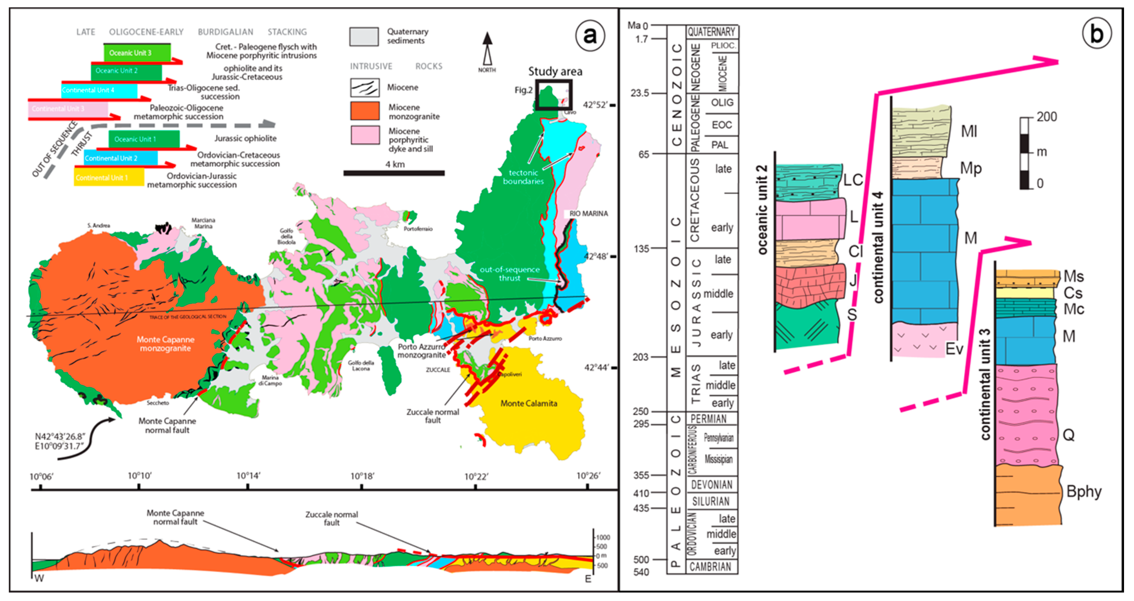
(a) Geological sketch map of Elba Island showing the seven tectonic units belonging to the collisional tectonic pile. The black solid square indicates the study area, enlarged Figure 2; (b) Tectono-stratigraphic columns in the study area: Oceanic Unit 2: S = ophiolite; J = radiolarite (Mt. AlpeChert Fm.); Cl = calcilutite and cherty limestone (Nisportino Fm.); L = cherty limestone (Calpionella Limestone Fm.); LC = limestone and shale (Palombini Shale Fm.). Continental Unit 4: Ev = evaporite (Calcare Cavernoso Fm.); M = massive and cherty limestone and dolostone (Pania di Corfino Fm., Mt. Cetona Fm., Calcare Massiccio Fm., Grotta Giusti Limestone, Rosso Ammonitico Fm., Limano cherty Limestone Fm.); Mp = marls (Posidonia Marlstone Fm.); Ml = Varicolored Shales (Cavo Fm.). Continental Unit3: Bphy = black phyllite (Rio Marina Fm.); Q = quartzite and phyllite (Verruca Fm., Mt. Serra quartzite Fm.); M = marble (Valle Giove Limestone Fm.; Capo Pero Limestone Fm.; Capo Castello Calcschist Fm.); Mc = cherty marble; Cs = calcschist and phyllite (Varicoloured Sericitic Schist Fm.); Ms = metasandstone and phyllite (Pseudomacigno Fm.) Modified, after [32,33].
Figure 1.
(a) Geological sketch map of Elba Island showing the seven tectonic units belonging to the collisional tectonic pile. The black solid square indicates the study area, enlarged Figure 2; (b) Tectono-stratigraphic columns in the study area: Oceanic Unit 2: S = ophiolite; J = radiolarite (Mt. AlpeChert Fm.); Cl = calcilutite and cherty limestone (Nisportino Fm.); L = cherty limestone (Calpionella Limestone Fm.); LC = limestone and shale (Palombini Shale Fm.). Continental Unit 4: Ev = evaporite (Calcare Cavernoso Fm.); M = massive and cherty limestone and dolostone (Pania di Corfino Fm., Mt. Cetona Fm., Calcare Massiccio Fm., Grotta Giusti Limestone, Rosso Ammonitico Fm., Limano cherty Limestone Fm.); Mp = marls (Posidonia Marlstone Fm.); Ml = Varicolored Shales (Cavo Fm.). Continental Unit3: Bphy = black phyllite (Rio Marina Fm.); Q = quartzite and phyllite (Verruca Fm., Mt. Serra quartzite Fm.); M = marble (Valle Giove Limestone Fm.; Capo Pero Limestone Fm.; Capo Castello Calcschist Fm.); Mc = cherty marble; Cs = calcschist and phyllite (Varicoloured Sericitic Schist Fm.); Ms = metasandstone and phyllite (Pseudomacigno Fm.) Modified, after [32,33].

Figure 2.
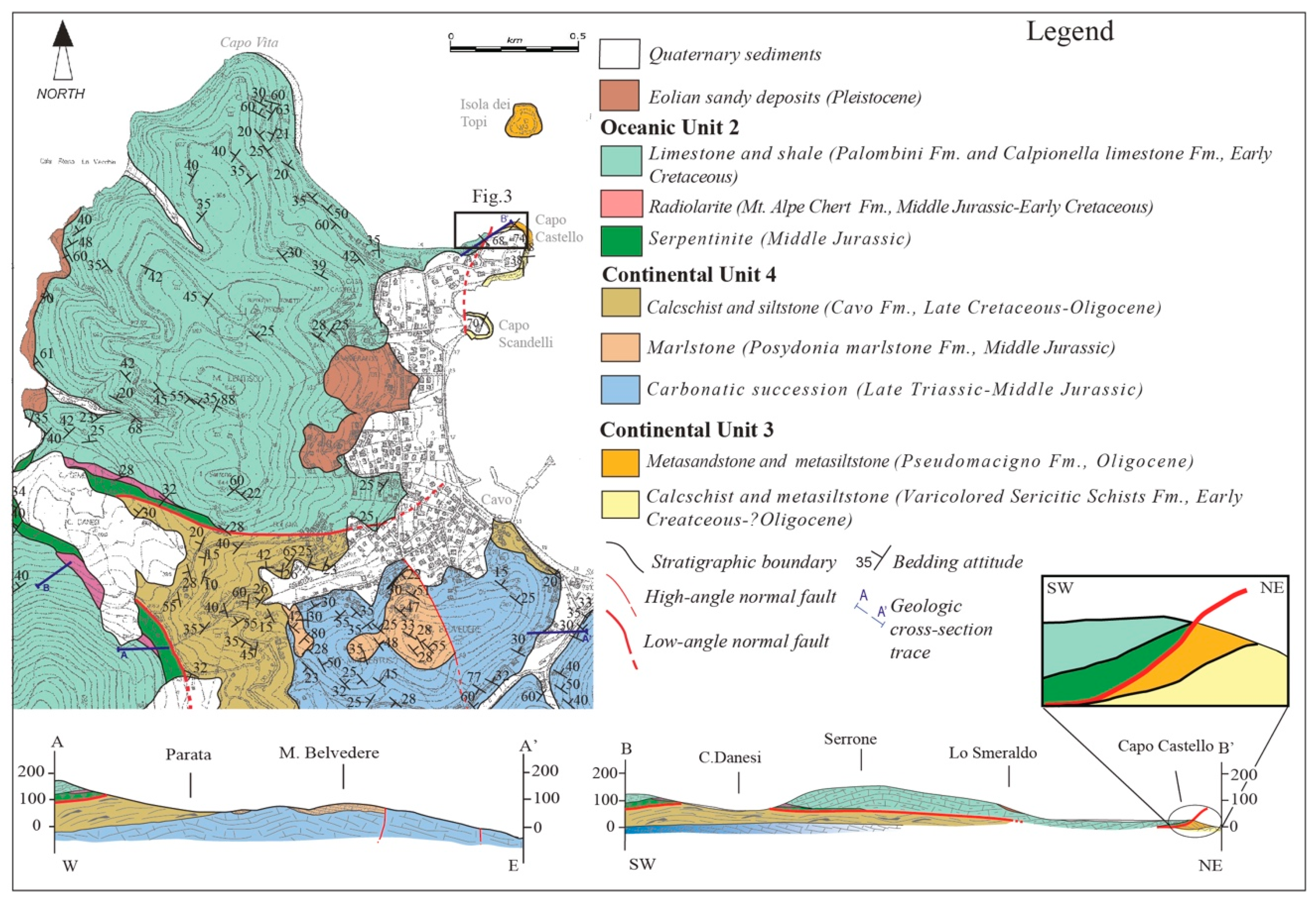
Geologic map and cross sections of the study area. The black square indicates the location Capo Castello shear zone. A schematic and not-to-scale cross section of the study shear zone (grey shade) is also showed, corresponding to the zoomed area within the BB’ cross section.
Figure 2.
Geologic map and cross sections of the study area. The black square indicates the location Capo Castello shear zone. A schematic and not-to-scale cross section of the study shear zone (grey shade) is also showed, corresponding to the zoomed area within the BB’ cross section.

Figure 3.
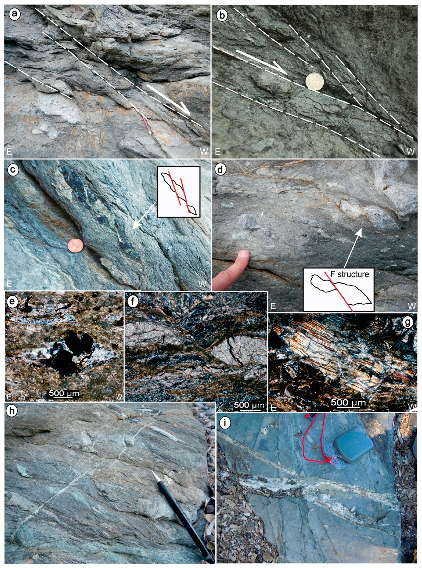
Capo Castello analyzed shear zone involving the quartzo-feldspathic rocks belonging to the Continental Unit 3 and the ophiolite-bearing rocks, with their sedimentary cover, belonging the Oceanic Unit 2. (a) Panoramic view of the study area with the boundary between different rock formations involved in the faulting and the scan line trace in black; (b) Protolith (i.e., the rock undeformed by the study shear zone) of calcschist and phyllite characterized by isoclinal folds; (c) metasandstones involved in the shear zone; (d) serpentinite level in the shear zone; (e) protolith with limestone and shale, structurally located over the serpentinite; (f) scan-line showing the lithology, and the distribution of the strain domains; (g) Structural data (lower hemisphere, Schmidt diagram) of the low and high strain domains. Stereoplots indicate cyclographic traces of C and S surfaces and of the brittle west-dipping structures F see the text for description; (h) Average stereoplots showing top-to-the ESE shear sense (to the right) and west dipping brittle structures (to the left).Structural and kinematic data are plotted in stereographic diagrams, lower hemisphere, equiareal projection. Stereograms were obtained by OSX Stereonet, from: http://www.geo.cornell.edu/geology/faculty/RWA/RWA.html.
Figure 3.
Capo Castello analyzed shear zone involving the quartzo-feldspathic rocks belonging to the Continental Unit 3 and the ophiolite-bearing rocks, with their sedimentary cover, belonging the Oceanic Unit 2. (a) Panoramic view of the study area with the boundary between different rock formations involved in the faulting and the scan line trace in black; (b) Protolith (i.e., the rock undeformed by the study shear zone) of calcschist and phyllite characterized by isoclinal folds; (c) metasandstones involved in the shear zone; (d) serpentinite level in the shear zone; (e) protolith with limestone and shale, structurally located over the serpentinite; (f) scan-line showing the lithology, and the distribution of the strain domains; (g) Structural data (lower hemisphere, Schmidt diagram) of the low and high strain domains. Stereoplots indicate cyclographic traces of C and S surfaces and of the brittle west-dipping structures F see the text for description; (h) Average stereoplots showing top-to-the ESE shear sense (to the right) and west dipping brittle structures (to the left).Structural and kinematic data are plotted in stereographic diagrams, lower hemisphere, equiareal projection. Stereograms were obtained by OSX Stereonet, from: http://www.geo.cornell.edu/geology/faculty/RWA/RWA.html.

Figure 4.
Area percentage occupied by porphyroclasts, as computed using image analysis. (a,b) quartzo-feldspathic protomylonite domain; (c,d) quartzo-feldspathic mylonitic domain; (e,f) myloniticserpentinite; (g,h) ultramylonite in serpentinite level. Srp: serpentine; Lit: lithic clast; Carb: carbonate clast; Mag: magnetite; Mgs: magnesite; Tlc: talc; Ultrm: ultramafic clast.

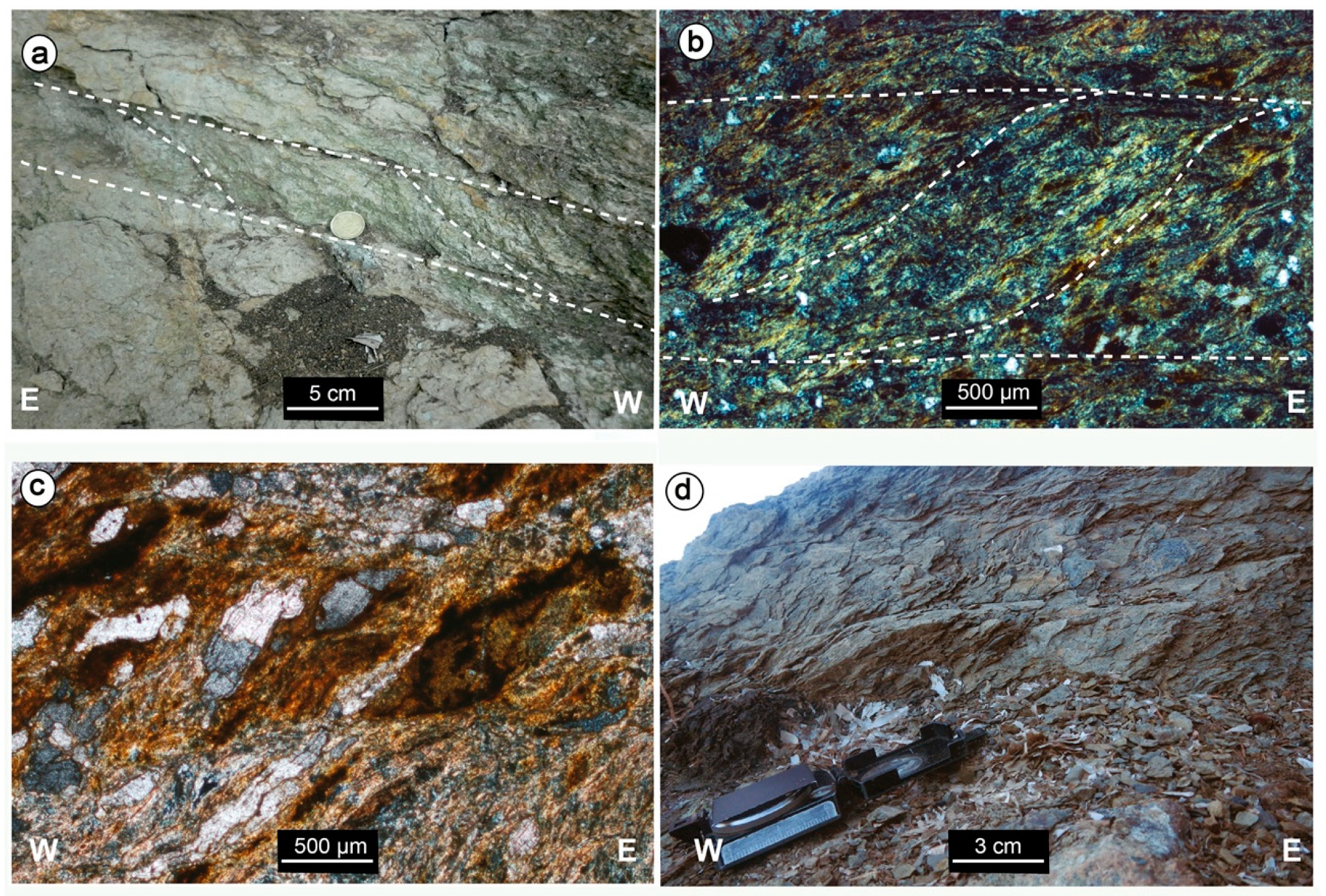
Figure 5.
Protomylonitic domains in the quartzo-feldspathic rocks (a–c) and in the (d) calcilutite of oceanic pertinence. (a) S/C structures with a top-to-the-east shear sense and related line drawing; (b) microscale S/C structures by micas and Fe-oxides and related line drawing; (c) crossed polars micrograph showing S surface underlined by magnesite ribbons, micas and Fe-oxides; (d); top-to-the-east S/C structures in the calcilutite.

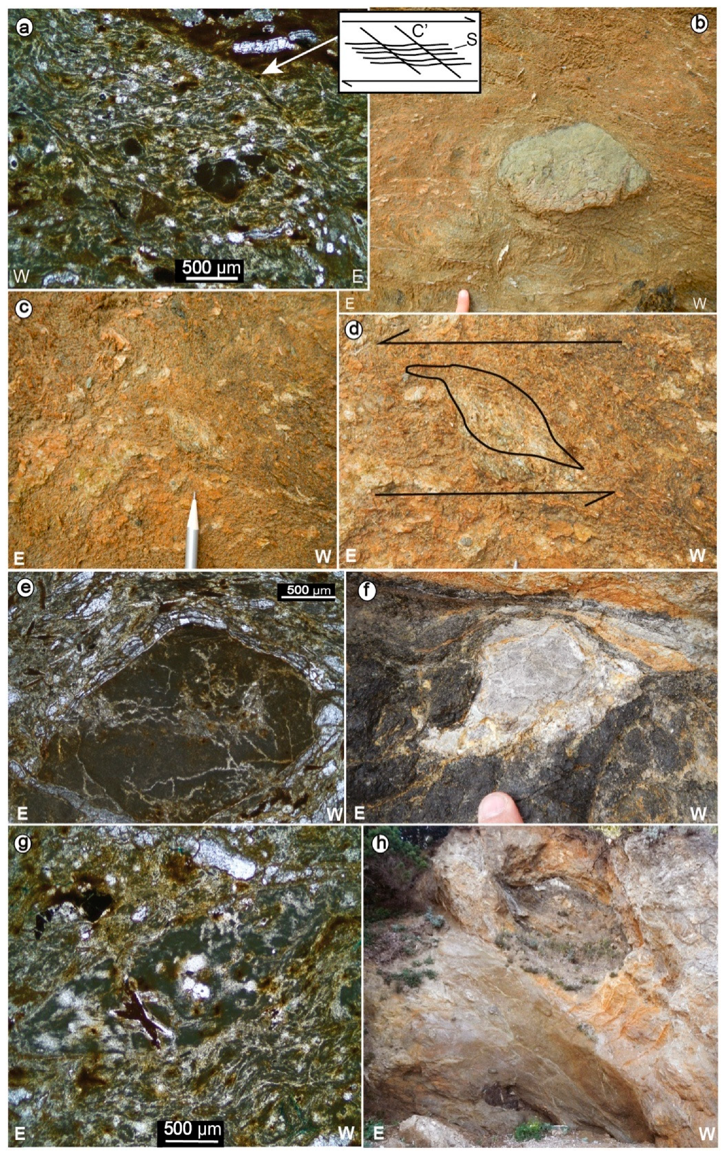
Figure 6.
Mylonitic domain within quartzofeldspathic rocks. (a) crossed polars micrograph of a highly foliated matrix with small porhyroclasts and shear bands; (b) isolated carbonatic porphyroclast; (c,d) sigmoidal carbonate porhyroclasts and its detail with the line drawing, pointing to a top-to-the east shear sense; (e) crossed polars micrographs displaying an altered lithic porphyroclast, affected by small carbonate veins and wrapped by magnesite ribbons; magnesite is also dispersed in the highly foliated matrix; (f) carbonate porphyroclast in a darker crystallized matrix; (g) crossed polars micrographs showing lithic porhyroclast dispersed in an intensely foliated and crystallized matrix. (h) large δ-type ultramafic porphyroclast pointing to a top-to-the east shear sense.

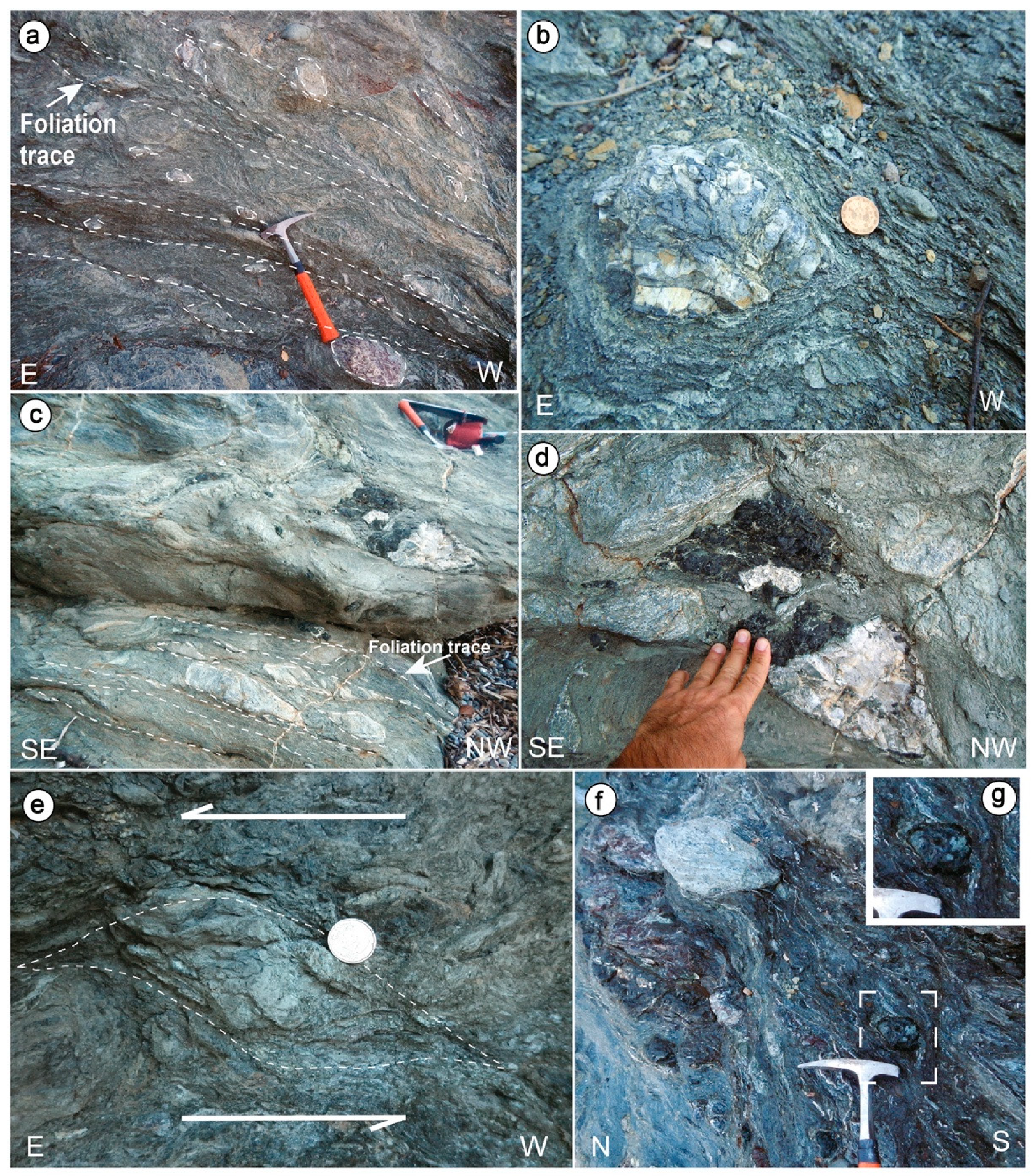
Figure 7.
Mylonitic domain in serpentinite rocks. (a–c) well expressed schistosity, in crystallized matrix with large porphyroclasts (predominantly of carbonate composition), aligned along the main foliation; (d,e) top-to-the-east carbonate and ultramafic porhyroclasts; (f) top-to-the-east δ-type ultramafic (enlarged in g) and carbonate porphyroclasts.

Figure 8.
Ultramyloniticserpentinite domain. (a,b) closely spaced top-to-the-east S/C and shear bands structures, respectively; (c) highly foliated matrix with tiny porphyroclasts aligned along the main schistosity; (d) Crossed polars micrograph showing an asymmetric magnetite porphyroclast with well evident strain shadow, mainly composed of talc and serpentine and pointing to a top-to-the-east shear sense; (e) crossed polars micrograph showing an asymmetric (top-to-the-east shear sense) magnesiteporphyroclast with a well evident strain shadow, mainly composed of talc; (f) rounded ultramafic porphyroclasts dispersed in a highly foliated matrix; (g) crossed polars micrograph showing an euhedral magnetite porphyroclast with a well-developed strain shadow, mainly composed of talc and serpentine.

Figure 9.
Raman spectra in the low-wave number region of (a) mixed lizardite and antigorite and (b) chrysotile.
Figure 9.
Raman spectra in the low-wave number region of (a) mixed lizardite and antigorite and (b) chrysotile.

Figure 10.
(a) sigmoids of serpentine and talc in the mylonitic serpentinite domain; tiny magnetite crystals are aligned along the main schistosity. Within the talc, small dolomite minerals are recognizable; (b) magnesite δ-type porphyroclast with strain shadows filled by talc; (c) chrysotileveinlets cross cutting talc crystal; (d) microstructures pointing to plastic deformation accommodated by a dissolution–precipitation mechanism in the presence of weak minerals as talc and serpentine; (e) Interconnected network of talc and magnesite; (f) bastite texture (lizardite + fine-grained carbonate) with lamellar extinction and striations disposed along the cleavage planes of the original orthopyroxene in SEM/BSE image; (g) the same pseudomorphic texture under optical microscope (crossed nicols); (h) deformed mesh boundaries picked out by magnetite and characterizing the substitution of olivine crystal with serpentine (lizardite) and talc (optical microscope, crossed nicols); (i) vein filled with magnesite and having serrated boundaries indicating a reaction processes producing talc. Along the central axis of the vein, dolomite and talc in small amounts indicate dissolution–precipitation reactions producing talc.

Figure 11.
Brittle structures in the quartzo-feldspathic rocks. (a,b) West dipping faults dissecting the S/C structures and its corresponding line-drawing; (c,d) micrographs showing lithic porphyroclasts cross cut by small scale faults (crossed nicols); in (d) the porphyroclast is also wrapped by magnesite ribbons; (e) magnesite vein affected by fractures; (f,g) micrographs of fibrous, antitaxial extensional calcite; (h) blocky magnesite.

Figure 12.
Later brittle structures in ophiolites. (a) west-dipping normal fault zone; (b) west-dipping faults with calcite mineralization on their slip-planes; (c,d) carbonate and ultramafic porphyroclasts dislocated by west-dipping fault (F-structure); (e) crossed polars micrograph showing a sliced up magnetite porphyroclast; (f) crossed polars micrographs showing a magnesite porhyroclast cross cut by a west-dipping fault; (g) crossed polars micrograph showing a fragmented pyroxene cross cut by magnesite veins; (h) calcite veins overprinting previous brittle structures cross cutting porhyroclasts; (i) calcilutite cross cut by calcite veins with internal small regular elements, testifying a possible contribute of hydraulic pressure during the fracturing process.

Figure 13.
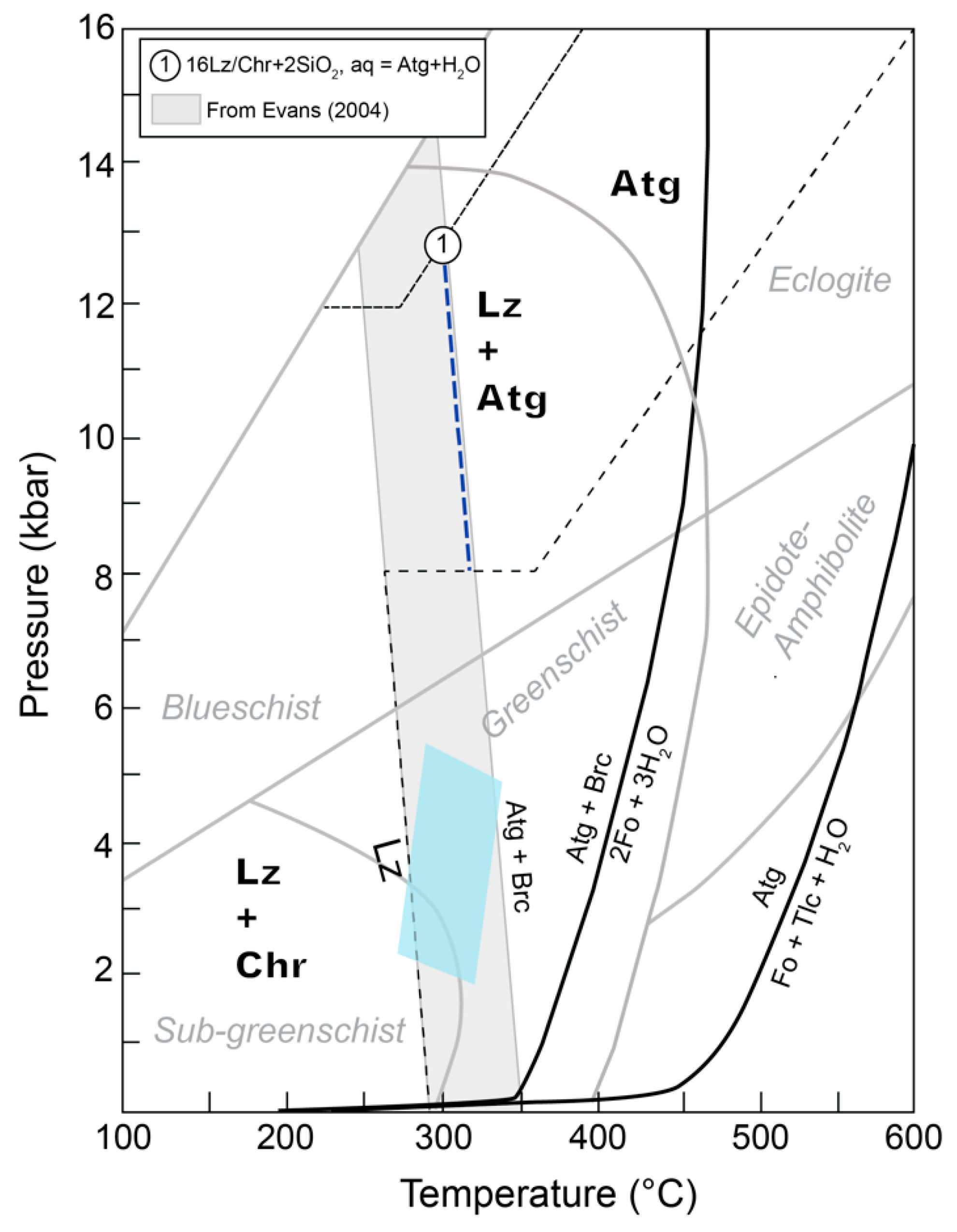
Phase diagram of antigorite and lizardite (from [69], modified). Symbols: Lz-lizardite, Atg-antigorite, Chr-chrysotile, Fo-forsterite, Tlc-talc, Brc-brucite. Reaction (1) is from [68] and occurs in the presence of SiO2-rich fluids by dissolution–precipitation processes. The pale blue area represents the coexisting lizardite and antigorite in the Capo Castello shear zone stability field.
Figure 13.
Phase diagram of antigorite and lizardite (from [69], modified). Symbols: Lz-lizardite, Atg-antigorite, Chr-chrysotile, Fo-forsterite, Tlc-talc, Brc-brucite. Reaction (1) is from [68] and occurs in the presence of SiO2-rich fluids by dissolution–precipitation processes. The pale blue area represents the coexisting lizardite and antigorite in the Capo Castello shear zone stability field.

Figure 14.
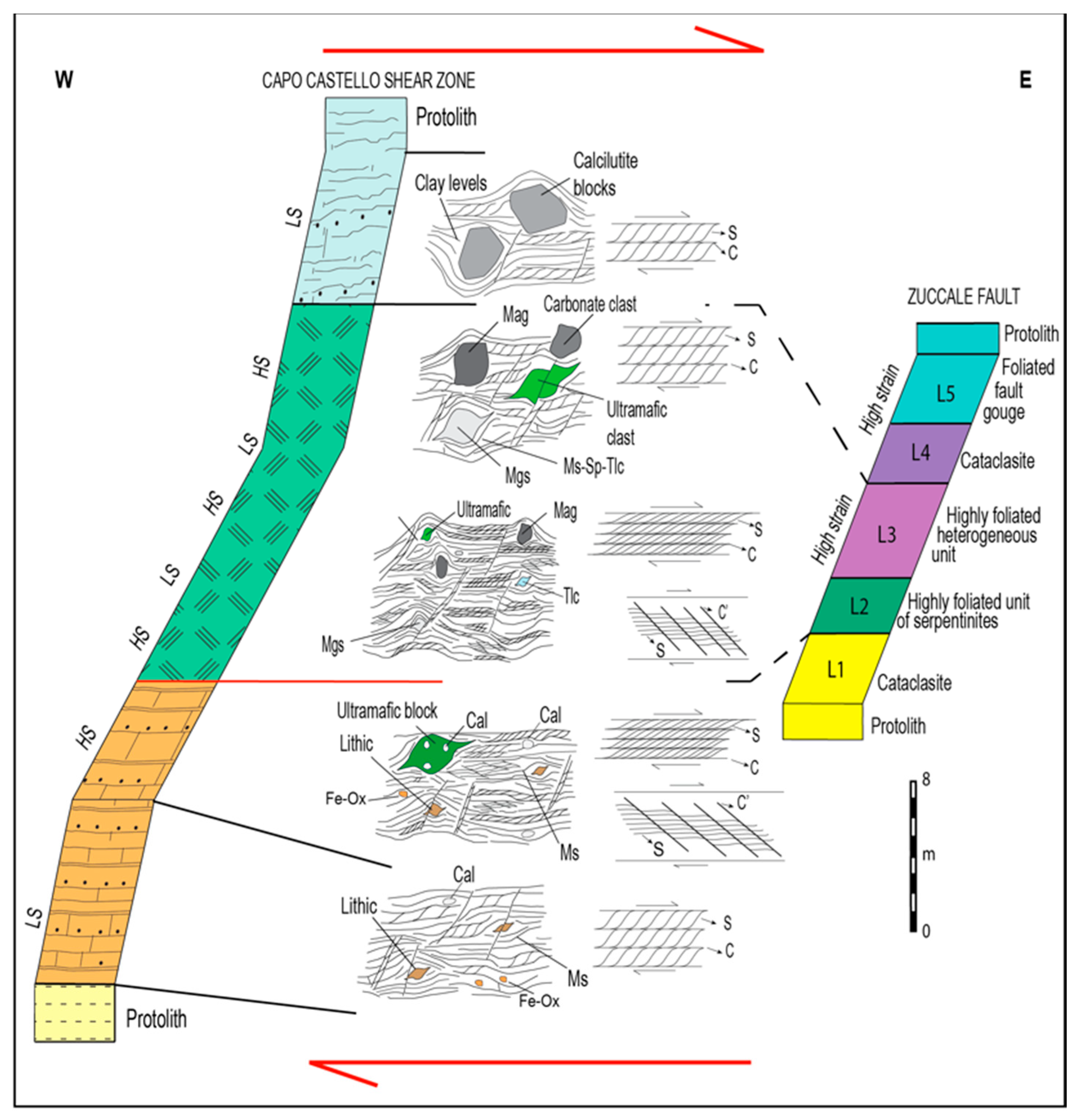
Sketch comparing the Capo Castello shear zone and the Zuccale normal fault stratigraphy. Along the Capo Castello shear zone log, the different strain domains are represented. The Zuccale normal fault log is reconstructed taking into account [56]. L1: cataclasite, locally with protomylonitic basement clasts, in a carbonate-quartz-chlorite matrix; L2: highly foliated unit of serpentinite plus tremolite-talc-chlorite schist; L3: highly heterogeneous unit of chlorite phyllonites with lenses of carbonate mylonite; L4: carbonate vein-rich unit set in a cataclasite with carbonate and ultramafic lenses; L5: foliated fault gouge and fault breccia. Deformation structures and deformation mechanisms of L2–L3 units are similar to the ones of the serpentinite levels in the Capo Castello shear zone.
Figure 14.
Sketch comparing the Capo Castello shear zone and the Zuccale normal fault stratigraphy. Along the Capo Castello shear zone log, the different strain domains are represented. The Zuccale normal fault log is reconstructed taking into account [56]. L1: cataclasite, locally with protomylonitic basement clasts, in a carbonate-quartz-chlorite matrix; L2: highly foliated unit of serpentinite plus tremolite-talc-chlorite schist; L3: highly heterogeneous unit of chlorite phyllonites with lenses of carbonate mylonite; L4: carbonate vein-rich unit set in a cataclasite with carbonate and ultramafic lenses; L5: foliated fault gouge and fault breccia. Deformation structures and deformation mechanisms of L2–L3 units are similar to the ones of the serpentinite levels in the Capo Castello shear zone.

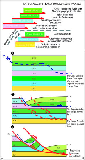
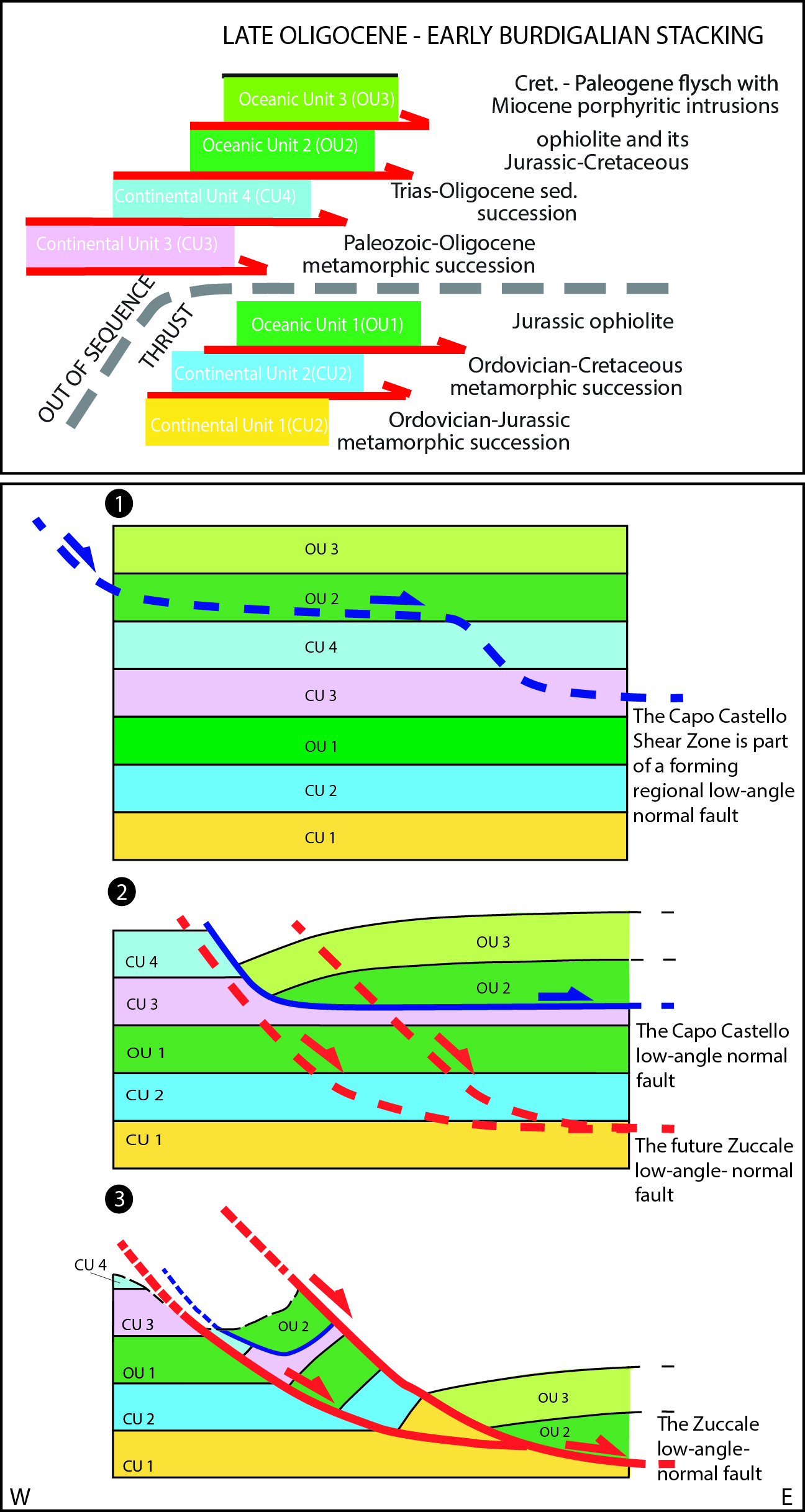
Figure 15.
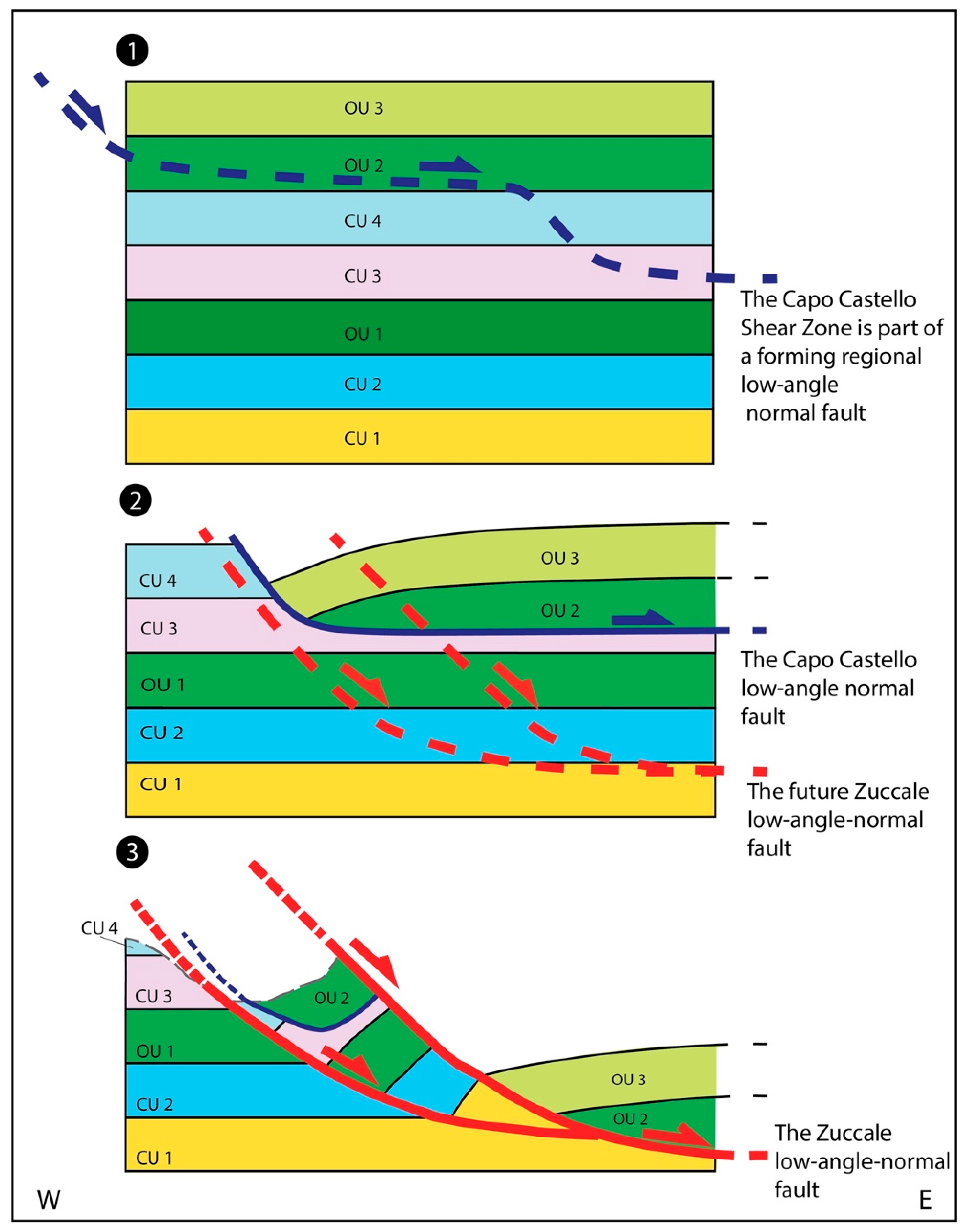
Tectonic scheme, not to scale, showing the tectonic omission, caused by the low angle normal fault to which the Capo Castello shear zone belongs, and its relationship with the low-angle Zuccale normal fault, in the stacked pile. From the top to the bottom: (1) the original Elba Island stacked pile linked to the Late Oligocene–early Miocene collisional phase; (2) the tectonic omission linked to the activity of the low angle normal fault to which the Capo Castello shear zone is associated; the Oceanic Unit 2 is in direct contact with the continental unit 3; (3) the tectonic omission generated by the Zuccale normal fault along which the Oceanic unit 3, the highest unit in the tectonic pile, overlay the deepest continental unit 1. Symbols indicate the Oceanic (OU) and the Continental Units (CU) stacked during the orogenesis. See also Figure 1.
Figure 15.
Tectonic scheme, not to scale, showing the tectonic omission, caused by the low angle normal fault to which the Capo Castello shear zone belongs, and its relationship with the low-angle Zuccale normal fault, in the stacked pile. From the top to the bottom: (1) the original Elba Island stacked pile linked to the Late Oligocene–early Miocene collisional phase; (2) the tectonic omission linked to the activity of the low angle normal fault to which the Capo Castello shear zone is associated; the Oceanic Unit 2 is in direct contact with the continental unit 3; (3) the tectonic omission generated by the Zuccale normal fault along which the Oceanic unit 3, the highest unit in the tectonic pile, overlay the deepest continental unit 1. Symbols indicate the Oceanic (OU) and the Continental Units (CU) stacked during the orogenesis. See also Figure 1.


Table 1.
Descriptive strain intensity Capo Castello shear zone domains within quartzo-feldspathic rocks and ophiolite, excluding the small level of ophiolite sedimentary cover.
Table 1.
Descriptive strain intensity Capo Castello shear zone domains within quartzo-feldspathic rocks and ophiolite, excluding the small level of ophiolite sedimentary cover.
| Lithology | Strain Intensity | Features |
|---|---|---|
| Quartzofeldspathic rock (metasandstone) | Low strain domain | Protomylonitic fabric Weak crystallized matrix (< 50%) Weak foliation Low frequency distribution of S/C structures Absence of shear bands (C’/C’’) Minor grainsize reduction Minor sintectonic mineral growth with weak preferred orientation Area covered by porphyroclasts: 0.8% |
| High strain domain | Mylonitic fabric Dark grey recrystallized matrix (between 50% and 90%) Intensely foliated High frequency of S/C structures Presence of C/C’’ shear bands Significantly grainsize reduction Moderate sintectonic mineral growth with moderate preferred orientation Porphyroclast with σ-shape, rare θ-type Area covered by porphyroclasts: 10% | |
| Ophiolite (serpentinite) | Low Strain domain | Mylonitic fabric Dark crystallized matrix (between 50% and 90%) Intensely foliated Moderate frequency distribution of S/C structures Absence of shear bands (C’/C’’) Moderate grainsize reduction Moderate sintectonic mineral growth with strong preferred orientation Porphyroclast with σ and ∂-shape Area covered by porphyroclasts: 13% |
| High strain domain | Ultramylonitic fabric Almost completely recrystallized matrix (<90%) Intensely foliated High frequency of S/C structures Presence of C/C’’ shear bands Intense grainsize reduction Pervasive sin-tectonic mineral growth with strong preferred orientation Porphyroclast ∂ and θ-shape area covered by porphyroclasts: 2% |
Table 2.
Representative mineral analyses in serpentinite gouge rock. Srp = serpentine; Tlc = talc; Mgs = magnesite; Mag = magnetite; Mg-Chr = magnesium-chromite; Cal = calcite; Dol = dolomite; Chl = chlorite, four types of chlorite (Penninite, Pycnochlorite, Chlinochlore and Sheridanite) have been detected. Structural formulae of Mag and Mg-Chromite have been calculated on the basis of 4 oxygens and 3 cations. Apart from the last two oxides, for all the minerals the total amount of Fe has been considered only as Fe2+CO3 has been calculated.
| Mgs | Cal | Dol | Tlc | Srp | Chl-Penninite | Chl-Oycnochlorite | Chl- Chlinochlore | Chl- Sheridanite | Mag | Mg-Chr | |
|---|---|---|---|---|---|---|---|---|---|---|---|
| SiO2 | 0.000 | 0.000 | 0.000 | 62.360 | 41.960 | 35.060 | 34.960 | 35.640 | 31.200 | 0.000 | 0.000 |
| TiO2 | 0.000 | 0.000 | 0.000 | 0.000 | 0.000 | 0.000 | 0.000 | 0.000 | 0.000 | 0.000 | 0.370 |
| Al2O3 | 0.000 | 0.000 | 0.000 | 0.470 | 2.210 | 16.440 | 20.070 | 24.300 | 27.200 | 0.000 | 4.900 |
| Cr2O3 | 0.000 | 0.000 | 0.000 | 0.000 | 0.410 | 0.000 | 0.000 | 0.000 | 0.000 | 0.000 | 32.400 |
| FeO | 8.520 | 0.870 | 0.770 | 1.910 | 3.340 | 11.200 | 19.790 | 1.870 | 3.500 | 92.410 | 46.380 |
| MnO | 0.260 | 0.230 | 0.370 | 0.000 | 0.000 | 0.000 | 0.000 | 0.000 | 0.000 | 0.000 | 0.000 |
| MgO | 38.970 | 2.710 | 16.070 | 29.320 | 38.440 | 30.250 | 19.860 | 33.700 | 31.080 | 0.410 | 14.450 |
| CaO | 0.980 | 45.490 | 27.510 | 0.000 | 0.000 | 0.080 | 0.360 | 0.360 | 0.360 | 0.180 | 0.000 |
| Na2O | 0.000 | 0.000 | 0.000 | 0.000 | 0.000 | 0.830 | 0.580 | 0.780 | 0.780 | 0.000 | 0.000 |
| K2O | 0.000 | 0.000 | 0.000 | 0.000 | 0.000 | 0.120 | 0.160 | 0.180 | 0.180 | 0.000 | 0.000 |
| CO2 | 48.700 | 39.335 | 39.838 | ||||||||
| TOTAL | 97.430 | 88.635 | 84.558 | 94.060 | 86.360 | 93.980 | 95.780 | 96.830 | 94.300 | 93.000 | 98.500 |
| Si | 0.000 | 0.000 | 0.000 | 8.030 | 1.979 | 6.349 | 6.414 | 5.965 | 5.426 | 0.000 | 0.000 |
| Al | 0.000 | 0.000 | 0.000 | 0.071 | 0.123 | 3.509 | 4.340 | 4.793 | 5.575 | 0.000 | 0.009 |
| Ti | 0.000 | 0.000 | 0.000 | 0.000 | 0.000 | 0.000 | 0.000 | 0.000 | 0.000 | 0.000 | 0.189 |
| Cr | 0.000 | 0.000 | 0.000 | 0.000 | 0.015 | 0.000 | 0.000 | 0.000 | 0.000 | 0.000 | 0.835 |
| Fe3+ | 0.000 | 0.000 | 0.000 | 0.000 | 0.000 | 0.000 | 0.000 | 0.000 | 0.000 | 2.000 | 0.958 |
| Fe2+ | 0.214 | 0.027 | 0.023 | 0.206 | 0.132 | 1.696 | 3.037 | 0.262 | 0.509 | 0.969 | 0.307 |
| Mn | 0.007 | 0.009 | 0.011 | 0.000 | 0.000 | 0.000 | 0.000 | 0.000 | 0.000 | 0.000 | 0.000 |
| Mg | 1.747 | 0.153 | 0.891 | 5.628 | 2.703 | 8.167 | 5.432 | 8.408 | 8.058 | 0.024 | 0.702 |
| Ca | 0.032 | 1.811 | 1.076 | 0.016 | 0.000 | 0.016 | 0.071 | 0.065 | 0.067 | 0.007 | 0.000 |
| Na | 0.000 | 0.000 | 0.000 | 0.291 | 0.000 | 0.291 | 0.206 | 0.253 | 0.263 | 0.000 | 0.000 |
| K | 0.000 | 0.000 | 0.000 | 0.028 | 0.000 | 0.028 | 0.037 | 0.038 | 0.040 | 0.000 | 0.000 |
| Σcations | 2.000 | 2.000 | 2.000 | 13.935 | 4.952 | 20.056 | 19.538 | 19.784 | 19.938 | 3.000 | 3.000 |
| CO3 | 2.000 | 2.000 | 2.000 | ||||||||
| XMg | 0.874 | 0.077 | 0.445 | 0.965 | 0.954 | 0.828 | 0.641 | 0.970 | 0.941 | 0.024 | 0.696 |
© 2020 by the author. Licensee MDPI, Basel, Switzerland. This article is an open access article distributed under the terms and conditions of the Creative Commons Attribution (CC BY) license (http://creativecommons.org/licenses/by/4.0/).
Share and Cite
MDPI and ACS Style
Bianco, C. The Capo Castello Shear Zone (Eastern Elba Island): Deformation at the Contact between Oceanic and Continent Tectonic Units. Geosciences 2020, 10, 361. https://doi.org/10.3390/geosciences10090361
AMA Style
Bianco C. The Capo Castello Shear Zone (Eastern Elba Island): Deformation at the Contact between Oceanic and Continent Tectonic Units. Geosciences. 2020; 10(9):361. https://doi.org/10.3390/geosciences10090361
Chicago/Turabian StyleBianco, Caterina. 2020. "The Capo Castello Shear Zone (Eastern Elba Island): Deformation at the Contact between Oceanic and Continent Tectonic Units" Geosciences 10, no. 9: 361. https://doi.org/10.3390/geosciences10090361
Note that from the first issue of 2016, this journal uses article numbers instead of page numbers. See further details here.