Article

Minerals in the Ash and Slag from Oxygen-Enriched Underground Coal Gasification

School of Chemistry and Environmental Engineering, China University of Mining and Technology (Beijing), Beijing 100083, China
*
Author to whom correspondence should be addressed.
Minerals 2016, 6(2), 27; https://doi.org/10.3390/min6020027
Submission received: 30 October 2015 / Revised: 19 January 2016 / Accepted: 21 January 2016 / Published: 30 March 2016
(This article belongs to the Special Issue Minerals in Coal)

Abstract

:
Underground coal gasification (UCG) is a promising option for the recovery of low-rank and inaccessible coal resources. Detailed mineralogical information is essential to understand underground reaction conditions far from the surface and optimize the operation parameters during the UCG process. It is also significant in identifying the environmental effects of UCG residue. In this paper, with regard to the underground gasification of lignite, UCG slag was prepared through simulation tests of oxygen-enriched gasification under different atmospheric conditions, and the minerals were identified by X-Ray diffraction (XRD) and a scanning electron microscope coupled to an energy-dispersive spectrometer (SEM-EDS). Thermodynamic calculations performed using FactSage 6.4 were used to help to understand the transformation of minerals. The results indicate that an increased oxygen concentration is beneficial to the reformation of mineral crystal after ash fusion and the resulting crystal structures of minerals also tend to be more orderly. The dominant minerals in 60%-O2 and 80%-O2 UCG slag include anorthite, pyroxene, and gehlenite, while amorphous substances almost disappear. In addition, with increasing oxygen content, mullite might react with the calcium oxide existed in the slag to generate anorthite, which could then serve as a calcium source for the formation of gehlenite. In 80%-O2 UCG slag, the iron-bearing mineral is transformed from sekaninaite to pyroxene.

1. Introduction

Coal, the main energy resource in China, accounts for approximately 70% of the primary energy resource structure. To avoid environmental pollution, the development of methods for clean and efficient utilization of coal has become necessary in recent years. During coal combustion and gasification at high temperatures, the reactivity differences of organic matters in coal can be almost ignored while the transformation behavior of minerals becomes important to the stability of the process. The reactions of inorganic minerals during combustion and gasification include a series of complicated physical and chemical changes that eventually form ash and slag with complex compositions [1]. Hence, detailed information about the mineralogical properties of coal ash is essential to optimize the operation parameters during coal utilization. It is also significant for improving the coal utilization efficiency and determining the influence of the solid wastes on the environment.
Underground coal gasification (UCG) is the process of in situ conversion of coal directly into combustible gaseous products. A sketch of the UCG process is shown in Figure 1. The first step of UCG is to choose a proper location and then design and construct an underground reactor. Boreholes are drilled from the surface to the coal bed, followed by a horizontal channel connecting the boreholes along the bottom of the coal bed. After a gasifier is prepared, the coal at one end of the channel is ignited, and gasification agents such as air, oxygen, steam, or their mixtures with different oxygen ratios are injected into the reactor. Accompanied by a series of coal reactions including pyrolysis, reduction, and oxidation, the fire moves along the channel towards the production borehole where the coal gas is collected by a pipeline. Unlike traditional coal mining and ground coal gasification technologies, UCG is carried out in the underground coal bed without physical coal mining, transportation, or coal preparation, which is regarded as supplementary to the coal mining method. The composition and heat value of the product gas depend on the initial gas injected, the position for gas injection, and the temperature profile of the coal bed.
Because UCG is always performed within the coal bed, several hundred meters beneath the surface, only the injection and production parameters can be determined. It is particularly difficult to determine the actual reaction conditions, especially the temperature field distribution and thermal equilibrium of the underground gasifier. Therefore, it is necessary to investigate the relationship between gasification technology and mineralogical characteristics of ash and slag through UCG simulation experiments. On the other hand, the potential for groundwater pollution from UCG-generated residues has also been a concern in recent years. The leaching behavior of toxic elements from solid residues is closely related to the characteristics of UCG ash and slag.
Plenty of research has been published on the conversion of minerals during coal combustion, but a low number of papers have reported on the transformation of minerals during coal gasification. Most of the study of ash chemistry during the high-temperature gasification process focused on the investigation of ash deposition and slag formation, as well as on the difficulties found in industrial gasifiers regarding fluidized bed gasification and entrained flow gasification [2,3,4,5]. However, few papers focus on the formation mechanism of ash and slag during the UCG process.
Mineral matter in coal can be classified as external minerals and inherent minerals according to their origin, with distinct differences in composition and form. At elevated temperatures, mineral transformation occurs, including chemical reactions between the clay minerals, carbonate minerals, pyrite, and quartz in the coal. It was discovered that the transformation temperature of external minerals was relatively lower than that of inherent minerals [6] and that the reaction rate and degree were greatly affected by temperature. Furthermore, the transformation processes varied in different gasification atmospheres. For instance, the softening temperature of minerals in the gasification condition was found to be lower than that in the combustion condition [7].
In addition to temperature and atmosphere, the furnace type is another important influence factor for ash formation behaviors [8]. The thermal conversion of minerals occurs at high temperatures (>800 °C) [9,10,11,12], including the transformation of clay minerals, carbonate minerals, pyrite, and quartz. During coal gasification, external minerals were fragmented into fine particles in the thermal conversion process, thus determining the particle size distribution of the fly ash. The formation of ash or slag is also enhanced by the cracking and thermal decomposition of external minerals as well as the reaction between external minerals and other minerals/gaseous substances [13]. A large number of studies show that pyrite and calcium carbonate break up when heated, while quartz and clay minerals do not. In addition, the breaking mechanism of some other types of external minerals is controversial and is affected by the residence time and heating rate [14,15,16,17,18]. The fusible minerals, such as the carbonate, sulfate minerals, and feldspar contained in inherent or external minerals, tend to become “solvent minerals” at high temperatures, which in turn promote the melting and slagging of gasification residues [19].
There are few reports on the formation and properties of UCG slag. In the USA, a series of residues and rocks were sampled from the UCG test site near Centralia, Washington [20]. X-Ray diffraction (XRD) and a scanning electron microscope coupled to an electron microprobe (SEM-EPMA) were used to analyze the mineralogical characteristics of the samples, and a moderate temperature reaction was confirmed. Reduced iron reacted with clay minerals to form a solid solution of aluminum-rich hercynite (FeAl2O4), which then serve as the precursor and react with SiO2 to form sekaninaite (Fe2Al4Si5O18) at higher temperatures.
In this study, based on the first UCG field test of lignite in Inner Mongolia, laboratory UCG simulation tests were performed to prepare UCG residues in different atmospheres. XRD and a scanning electron microscope coupled to an energy-dispersive spectrometer (SEM-EDS) were used to identify the composition and microstructure of the typical minerals formed and existing in UCG ash and slag. Thermodynamic calculations using FactSage 6.4 (Thermfact/CRCT, Montreal, QC, Canada; GTT-Technologies, Aachen, Germany) were also carried out to investigate the transformation of minerals at elevated temperatures during the UCG process.

2. Experimental and Modeling

2.1. Geological Setting of the Coalfield

The strata in the study area are from the Lower Jining Group in the Mesoarchean (Ar2J1), the Oligocene Huerjing Formation (E3h), the Miocene Hannuoba Formation (N1h), the Pliocene Baogedawula Formation (N2b), and the Holocene. The coal-bearing strata are a set of sedimentary sequences of terrestrial clastic rocks formed in lake and swamp facies and overlain by the Quaternary strata. In addition, the Jining Group is the basement of the coal-bearing strata, and the major lithology is granite at depths of 202.95–565.25 m.
The main coal bed in this area occurs in the Lower Huerjing Formation (E3h1). It is 7.05 m thick on average and minable in most coalfields, with 0–12 partings of accumulative thickness in 1.79 m. The dip angle of the coal bed is less than 5°. The roof of the coal bed is siltstone and dark grey carbonaceous mudstone with clastic organic debris, while the bottom of the coal bed is a thin layer of mudstone close to the lowest basement of granite and gneiss. The coal is identified as lignite, with an ignition point of 268 °C and the net heating value ranging from 13.37 to 16.72 MJ/kg [21].

2.2. Coal Samples

The test lignite is from a neighboring coal mine of the UCG field test area, also in the Gonggou coal field located in Ulanqab, Inner Mongolia, China. The coal bed has an average depth of 280 m.
Proximate analysis, including moisture, ash, volatile matter, and fixed carbon, was determined in accordance with Chinese Standards GB/T 212-2008 [22]. Ultimate analysis, including carbon, hydrogen, nitrogen, and total sulfur, was measured following Chinese Standards GB/T 476-2008 [23], GB/T 19227-2008 [24] and GB/T 214-2007 [25], respectively. The results of the ultimate and proximate analyses of the coal sample are shown in Table 1, indicating that the lignite is higher in volatile materials, ash and moisture. With a sulfur content lower than 1%, the test lignite is considered a low-sulfur coal according to Chinese standards GB/T 15224.2-2010 [26].
The ash composition of the test lignite was conducted using GB/T 1574-2007 [27], which expressed in oxide percentages (Table 2). The ash fusion test is performed according to Chinese standards GB/T 219-2008 [28].
It is obvious that the lignite is enriched in SiO2, Al2O3 and CaO. Among them, SiO2 accounts for more than half of the composition, followed by Al2O3 with a ratio of 18.02%. The content of Fe2O3 and SO3 are relatively high in this sample and account for 5.83% and 2.50%, respectively. The analysis results of the coal ash fusibility in a weak reducing atmosphere are exhibited in Table 3. It can be seen that the coal ash is medium melting, beginning to soften at approximately 1200 °C and starting to flow at approximately 1270 °C.

2.3. Underground Coal Gasification (UCG) Simulation Facility

The UCG simulation facility, as shown in Figure 2, consists of four parts: the gasifier gas supply system, the gas cleaning system, the sampling, and monitoring systems. The whole gasifier is designed in the shape of a cylinder with external dimensions of 7.4 m in length and 3.5 m in diameter. The shell of the gasifier is made of special steel used for pressure vessels, and the design pressure is 1.6 MPa. The hearth of the reactor is cast with refractory material in the shape of a rectangular prism (5.0 m × 1.6 m × 1.6 m), the working temperature of which can be up to 1800 °C. Five inlet or outlet pipes, 33 measurement points for temperature and pressure, and four observation holes for a closed circuit industrial television (CCTV) are installed in the reactor. Gas composition analysis is performed by gas chromatography (GC-2014, Shimadzu, Kyoto, Japan). Data are collected online during the test using a distributed control system (DCS) (Honeywell, Morristown, NJ, USA) and saved to a hard disk. Various curves for parameters can be transferred to the screen from the DCS.

2.4. Coal Bed Simulation

The coal bed layout is shown in Figure 3. A soil layer with a thickness of 50 mm was arranged at the bottom of the hearth of the test gasifier to act as the bottom layers. Then, coal lumps with dimensions of 0.4 m × 0.8 m × 0.8 m were piled into the internal hearth to create a coal bed of 0.8 m in length, 0.8 m in width and 3.5 m in height. The gaps between the coal blocks were filled with coal slurry, which is a mixture of coal powder and clay. Then, a square channel with dimensions of 0.1 m × 0.1 m was drilled into the bottom of the coal bed and connected to the vertical inlet and outlet holes. In the following step, the coal bed was covered by a 2-cm sand layer and then cast with a thin layer of cement. Finally, the gap between the cement and the hearth was tightly filled with soil to prevent gas leakage.
To monitor and control the temperature profile in the gasified coal bed during the test, 63 K-type armored thermocouples were installed in the coal bed and arranged in three levels, 0.15-m, 0.3-m or 0.4-m below the top of coal bed. In each level, 21 thermocouples were laid with an average distribution.

2.5. Experimental Procedure

The UCG method of controlled moving injection point was used to perform gasification in order to change the oxygen concentration in the injection gas. After a leak test of the UCG simulation facility, the gasifier was prepared for ignition. First, air was introduced into the channel through the injection hole. Then, an electric igniter was placed inside the horizontal channel and used to ignite the coal. The temperature was monitored and collected in real time, and the gas from the production hole was analyzed every 20 min. If the temperature in the coal bed increased to 600 °C and the concentration of CO2 in the effluent gas exceeded 20%, this suggested that the ignition was successful. Then, the gas mixture containing 40%-O2 and 60%-N2 was injected into the gasifier to produce gas. With the expansion of the cavity, the high-temperature zone, or fire face, moves towards the production hole. When the gas quality grew poor, as determined by a gas heat value lower than 4.18 MJ/m3, we switched to the second injection hole nearest the fire face, and a mixture of 60%-O2 and 40%-N2 was injected. The entire duration lasted for 80 h, including 10 h for ignition and preheating, 30 h for 40%-O2 gasification, 20 h for 60%-O2 gasification, and 20 h for 80%-O2 gasification. After the three-stage simulation test, N2 was continuously injected to cool the gasifier.

2.6. Sampling and Analysis of UCG Slag

2.6.1. Sampling of UCG Slag

After the temperature inside the furnace reached room temperature, the gasifier cover was opened. The sandy soil above the coal bed was removed carefully, and slag formed under different UCG conditions was collected near the injection point for analysis. Pictures of the UCG cavity and UCG slag in different atmospheres are shown in Figure 4.

2.6.2. X-Ray Diffraction (XRD) Analysis

The raw coal, ash, and slag were crushed, ground, and sieved before analysis. Samples below 75 μm were selected for XRD analysis, which was performed on a powder diffractometer (D/max-2500/pc XRD, Rigaku, Tokyo, Japan) with Ni-filtered Cu-Kα radiation and a scintillation detector. The XRD pattern was recorded over a 2θ range of 2.6°–70° at a scan rate of 3°/min and a step size of 0.01°. Jade 6.5 software (MDI, Livermore, CA, USA) was used to analyze the XRD curve for qualitative analysis. X-Ray diffractograms of the LTAs (low temperature ash) and partings were subjected to quantitative mineralogical analysis using Siroquant™ ( Sietronics, Mitchell, Australia), a commercial interpretation software developed by Taylor (1991), based on the principles for diffractogram profiling set out by Rietveld (1969). Further details indicating the use of this technique for coal-related materials are given by Ward et al. [29] and Dai et al. [30].

2.6.3. Scanning Electron Microscope and Energy-Dispersive Spectrometer (SEM-EDS) Analysis

The raw coal and ash and slag samples were firstly crushed and ground, and particles in the range of 1–3 mm were collected. The sample particles were then mixed with ethyl α-cyanoacrylate and the mixture was polished and mounted on standard aluminum SEM stubs using sticky electronic-conductive carbon tabs. A field emission-scanning electron microscope (FE-SEM, Quanta™ 650 FEG, FEI, Hillsboro, OR, USA), in conjunction with an energy-dispersive X-Ray (EDAX) spectrometer (EDS, Apex 4, Genesis, NJ, USA), was used to study the morphology of the minerals and to determine the distribution of some elements. The samples were prepared under low-vacuum SEM conditions. The analytical conditions were as follows: working distance (WD) 10 mm, beam voltage 20 kV, aperture 6, and micron spot size 5. The images were captured via a retractable solid state backscatter electron detector (SSBSED). More details of FE-SEM-EDS are described by Dai et al. [31].

2.7. FactSage Thermochemical Modeling

FactSage® (Thermfact/CRCT, Montreal, QC, Canada; GTT-Technologies, Aachen, Germany) was introduced in 2001 as the fusion of two well-known software packages in the field of computational thermochemistry: F*A*C*T/FACT-Win and ChemSage. The thermochemistry models can be used to analyze equilibrium conditions for reactions occurring between inorganic and/or organic materials, as well as providing insight into the mineral formation and slag formation speciation. The database can assist in understanding, as well as predicting, what can and will happen with specific coal and mineral sources inside the gasification process [32]. In this study, thermodynamic equilibrium modeling was accomplished by the “Equilib module” in FactSage 6.4, which is the Gibbs energy minimization workhorse of FactSage. It calculates the concentrations of chemical species when specific elements or compounds react or partially react to reach a state of chemical equilibrium [33].
For the calculations the equilibrium module has been employed together with the databases FToxid and FactPS. Additionally, the solution phases of FToxid-SLAG and FToxid-oPyr have been selected. In order to simulate the gasification process as close as possible to the actual gasification process, the temperature is from 0 to 1500 °C in 100 °C intervals and the pressure is atmospheric pressure. The calculations were conducted based on the mineral composition of coal and the amount of coal, oxygen, and nitrogen consumed to produce 1 N·m3 of gas. Since the amount of ash in coal is the sum of the mineral composition of coal such as SiO2, Al2O3, Fe2O3, TiO2, CaO, MgO, K2O, Na2O, MnO2, SO3 and P2O5, the input into FactSage as shown in Table 4 is done in elemental form i.e., carbon (C), hydrogen (H), nitrogen (N), sulfur (S), oxygen (O), and other mineral elements.

3. Results and Discussion

3.1. Gas Composition under Oxygen-Enriched Gasification Conditions

Increasing the oxygen concentration of the gasification agent is an effective way to improve the quality of the product gas. Table 5 provides detailed information about coal gas composition and gas heat value under oxygen-enriched gasification conditions during the UCG simulation test. The gas heat values and the contents of CO and H2 in the gas gradually increased with the increase in oxygen concentrations. The yield of CO and H2 mainly depends on the rate and extent of the reduction reaction between C and CO2/H2O (g), which is dominated by the temperature. Coal combustion was enhanced when a larger amount of oxygen was injected and the reduction process was strengthened, accompanied by an increase in the temperature field in the gasifier. This suggests that during UCG, an optimum oxygen concentration in the injection agent could be found to yield the highest combustible composition for certain coal types and typical reaction conditions. In addition, it was found that the methane content remains at a lower level and is less affected by the oxygen concentration.

3.2. Distribution of Temperature Field in the Coal Bed

During the UCG process, the transformation of the organic and inorganic components of the coal can be divided into three steps. The first step is the drying and pyrolysis of coal below 600 °C, which involves the release of water and volatile matter and the crystal transformation of some minerals. The second step is the reduction reaction of char with CO2 and H2O (g) at temperatures ranging from 600 to 900 °C. The final step is the oxidation of residual carbon above 900 °C. The real reaction temperature is much higher than the theoretical temperature because of the thermal storage in the simulated coal bed.
Temperature profiles of the coal bed under different oxygen-enriched conditions are displayed in Figure 5, Figure 6 and Figure 7 and were constructed from thermocouple data. It is clear that the high-temperature area is narrow in 40%-O2 and 60%-O2 conditions because their reduction and oxidation reactions occur in smaller areas. However, when the oxygen concentration was increased to 80%, the temperature field in the reaction area significantly increased. In the oxidation zone near the injection hole, the temperature was increased remarkably. In addition, most of the monitoring points exceeded 600 °C, and the maximum temperature of the central area of oxidation increased from 1200 to 1400 °C. It is inferred that the reduction area is enlarged and the reduction process is enhanced.

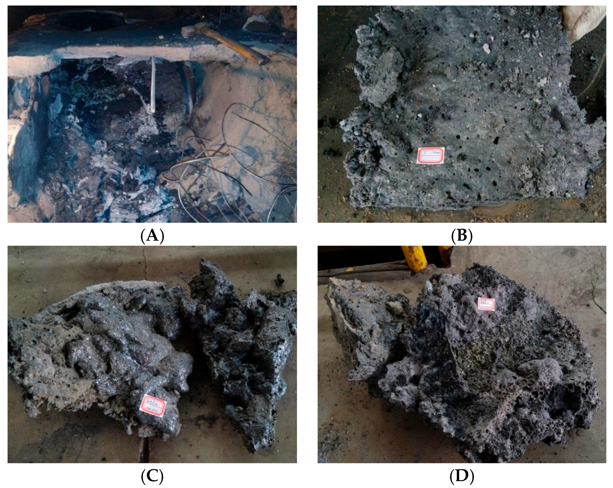
3.3. Minerals in the UCG Ash and Slag

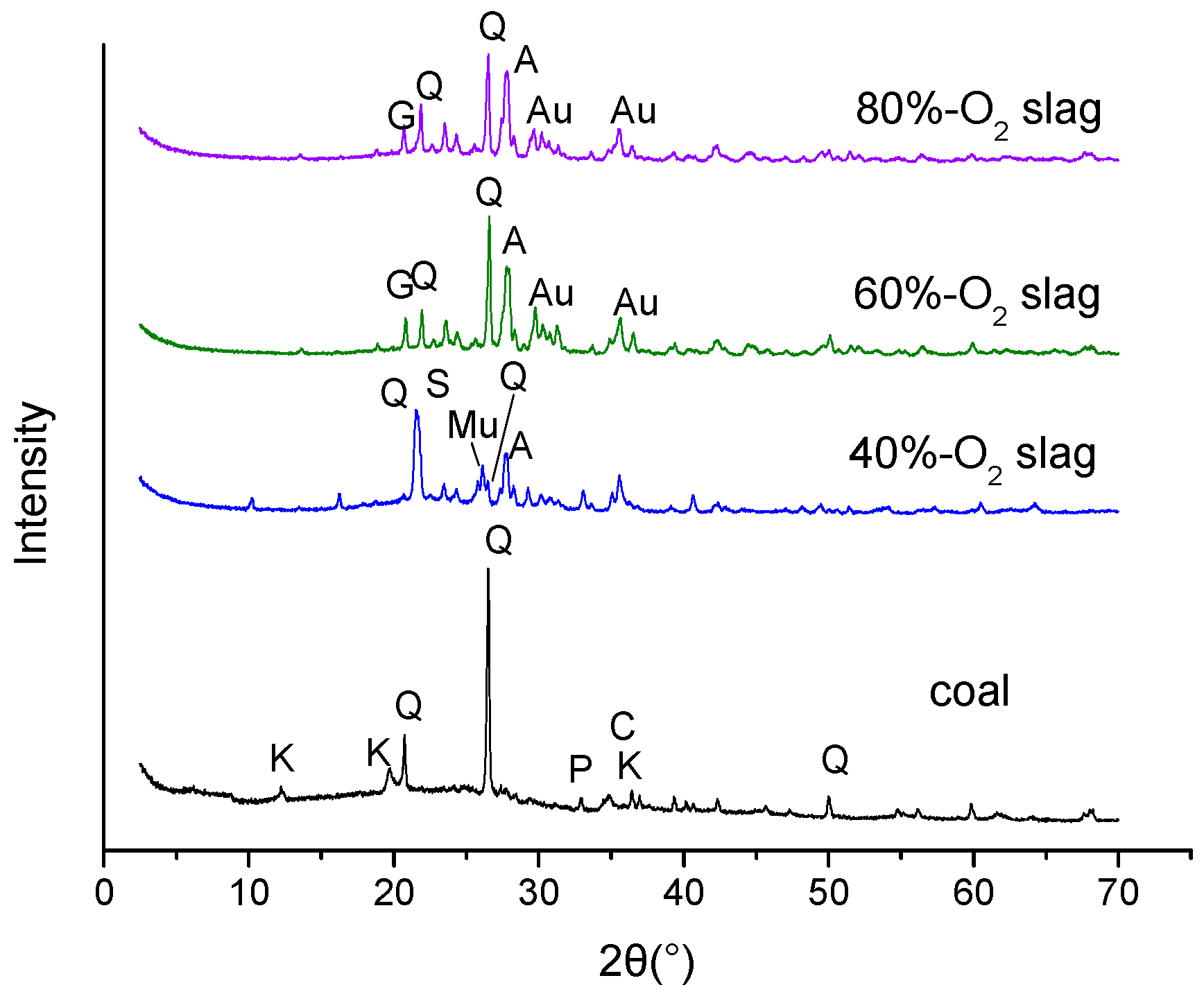
To further understand the mineral transformation behavior that occurs during the UCG process, X-Ray diffraction analysis was carried out to identify the typical minerals present in the UCG residual samples. The XRD patterns of raw coal and UCG slag at different atmospheres are summarized in Figure 8, and the quantitative analysis results using Siroquant are listed in Table 6. The major minerals found in raw coal include quartz (melting point (Tm): 1723 °C), illite, and clay minerals (mostly kaolinite). Minor amounts of pyrite and chlorite are also observed. In the 40%-O2 slag, high-temperature quartz, anorthite (Tm: 1550 °C), mullite (Tm: 1900 °C), sekaninaite (Tm: 1200 °C), and massive amorphous substance materials (49%) become the major minerals. The mineral compositions of 60%-O2 slag and 80%-O2 slag are similar, and the dominant minerals involve high-temperature quartz, anorthite, gehlenite (Tm: 1500 °C), and pyroxene. Furthermore, the amount of quartz and anorthite in 80%-O2 slag is less than that in 60%-O2 slag, while gehlenite is formed in great quantities. Clay and iron minerals in coal have not been found in UCG slag, which suggests that they have been transformed to anorthite and pyroxene during oxygen-enriched gasification.
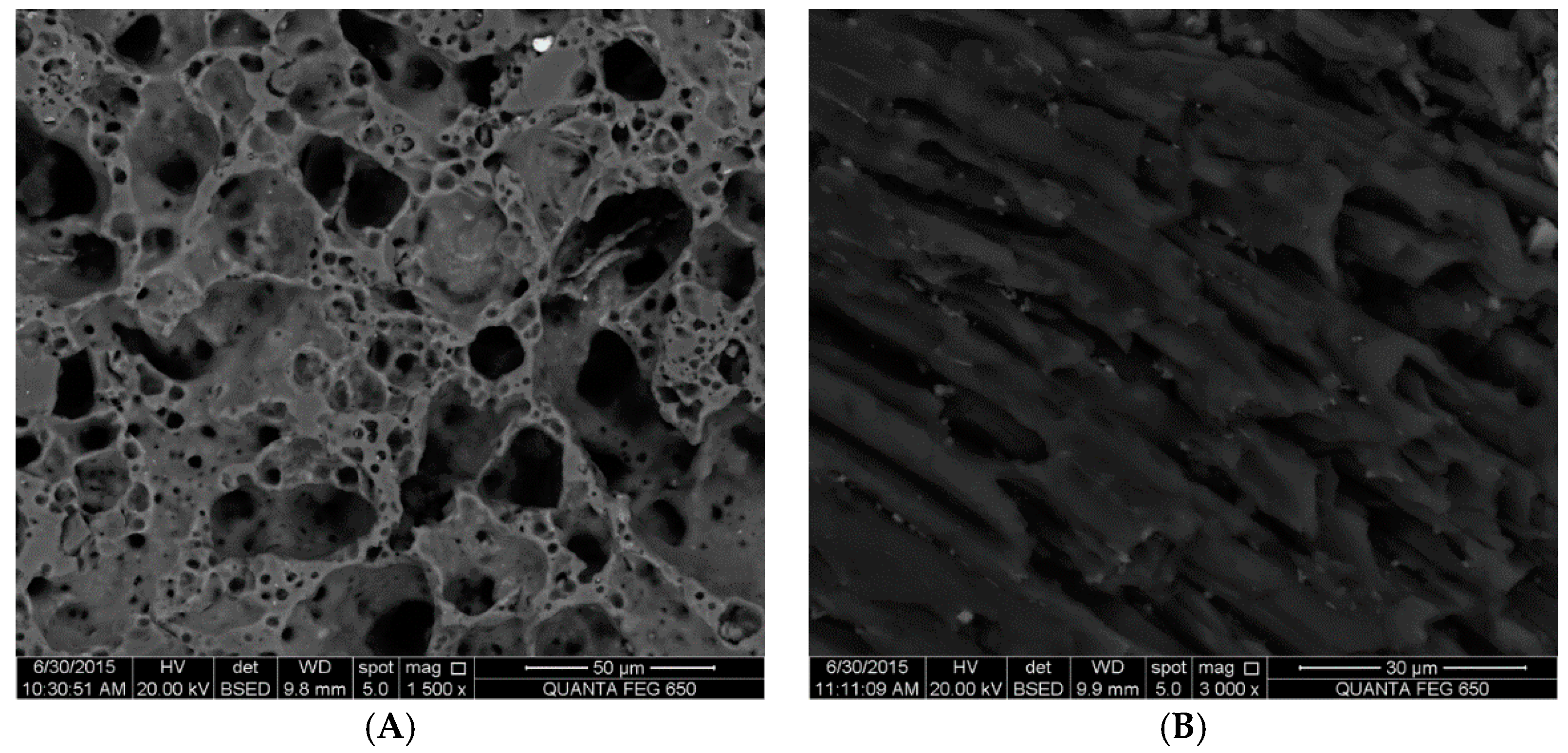
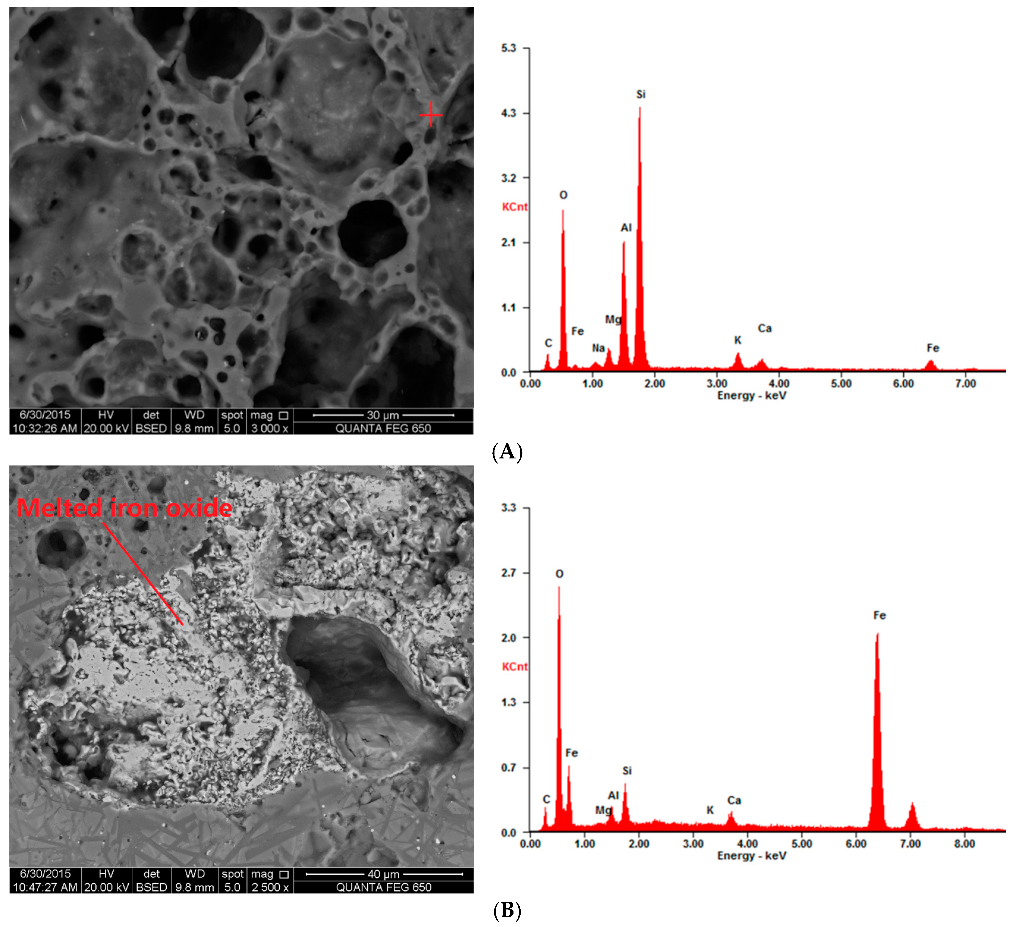
In addition to X-Ray diffraction analysis, SEM-EDS examination was also performed to investigate the typical minerals present in the UCG slag. A great deal of amorphous materials were identified in the 40%-O2 slag based on XRD analysis, which was also proven by SEM images, shown in Figure 9A, in which a large amount of porous and melted materials could be observed. It has been reported that during gasification, the decrease in crystallization intensity of the minerals with increasing temperature is not only due to the decomposition of some mineral phases, but also because of the formation of molten liquid(SLAG) [
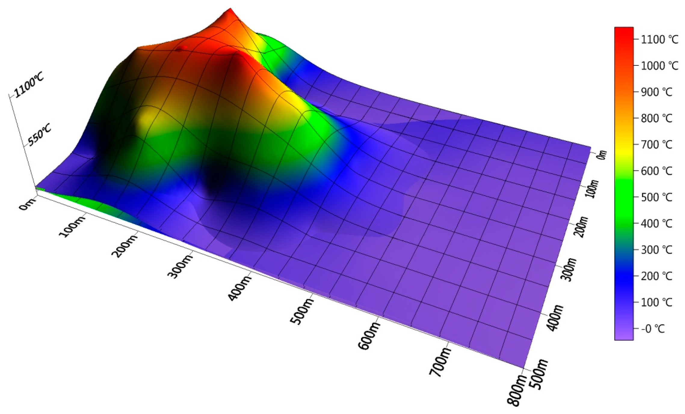
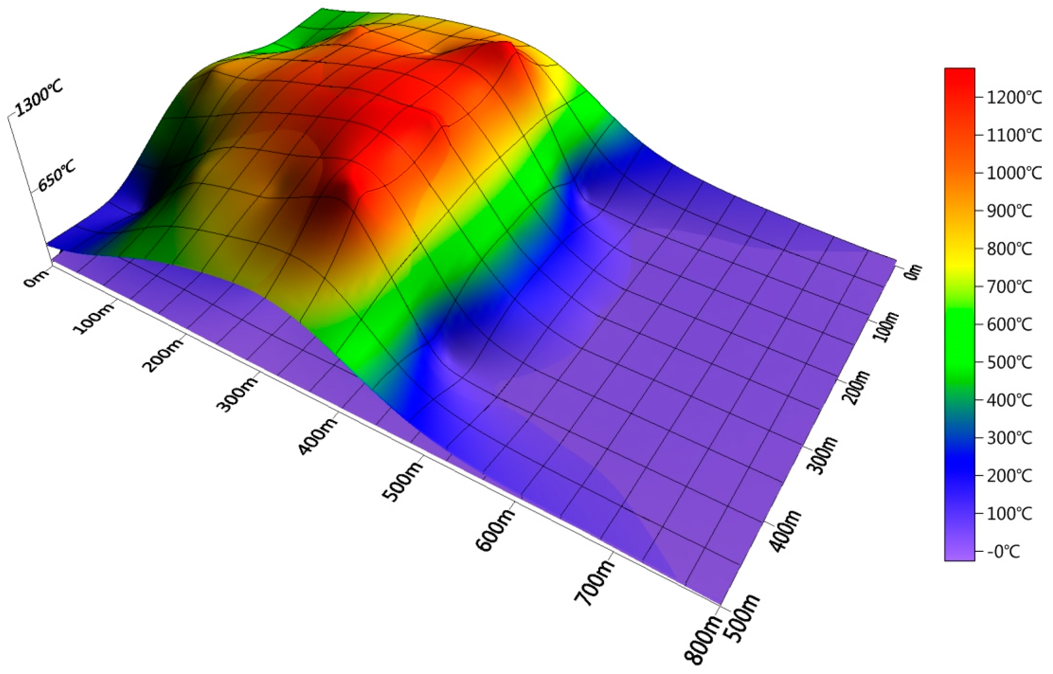
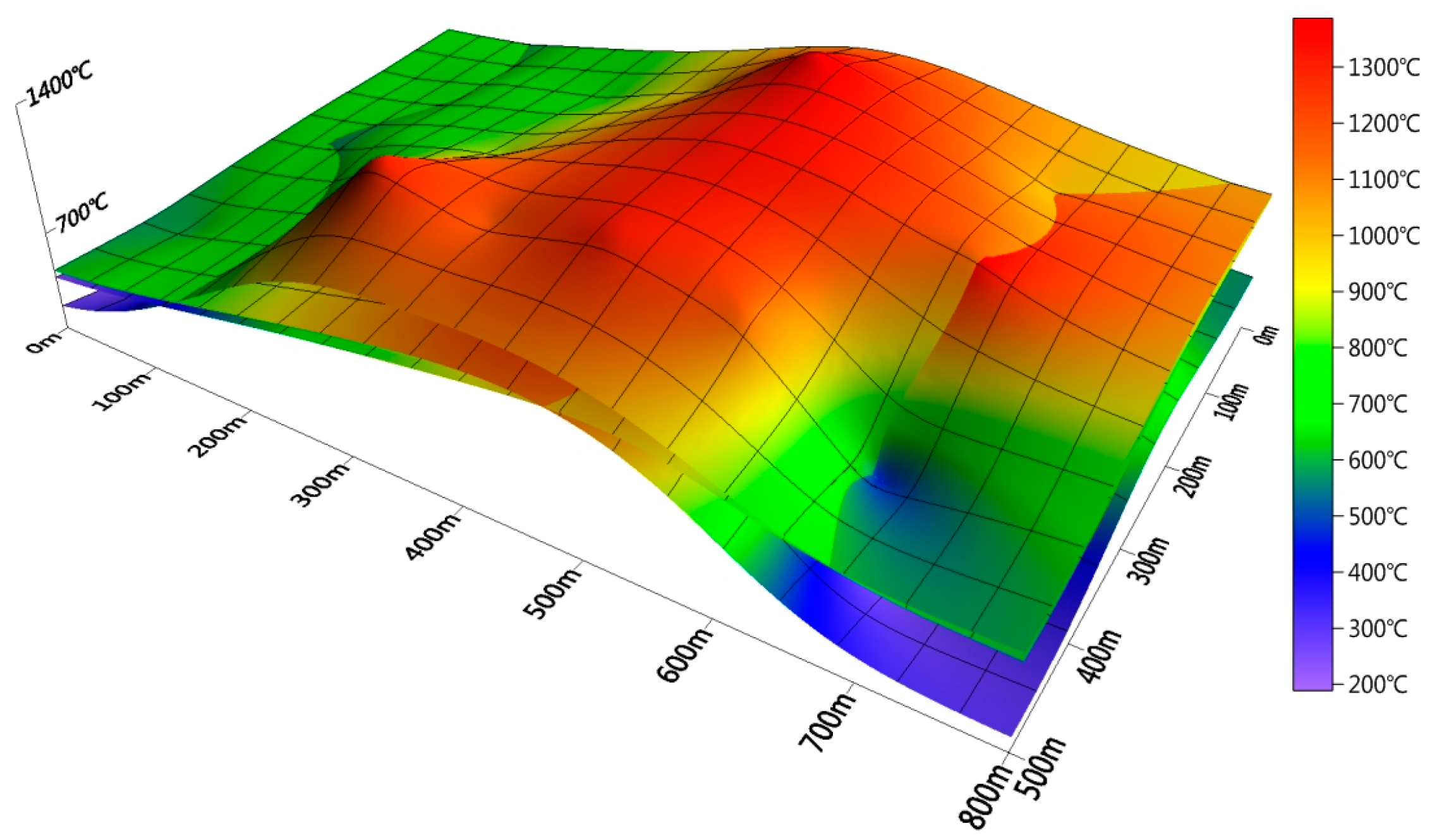
32]. Based on the previous information for temperature distribution in the 40%-O2 gasification condition, the temperatures in the oxidation zone are in the range of 1100 to 1200 °C, which is close to the ash fusion point of the test coal. Therefore, it is concluded that under this gasification condition, the minerals in coal might melt and then form slag after cooling down, leading to an obvious disappearance of crystal minerals. Simultaneously, a small portion of the crystal minerals could be encapsulated by the melting material.
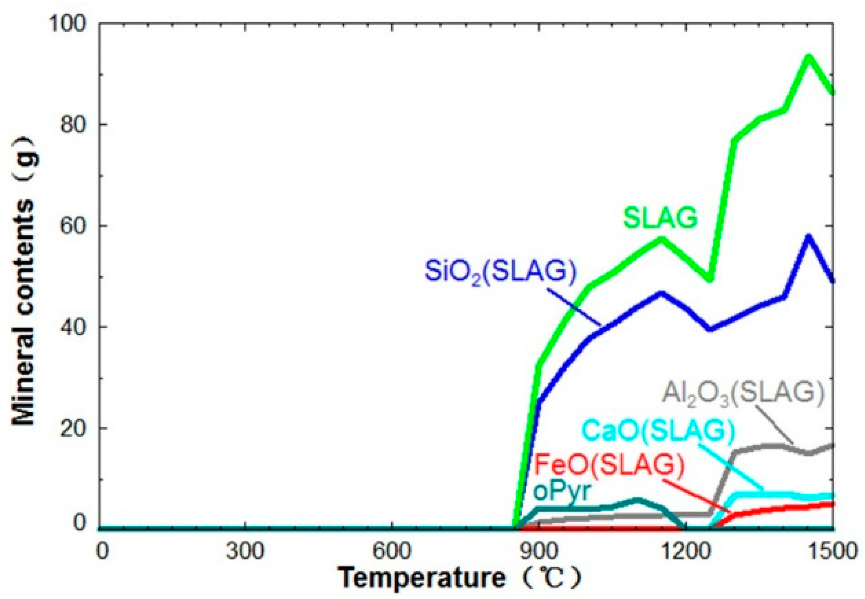
The mineral transformations with increasing temperature are displayed in Figure 10. It is indicated that in the 40%-O2 gasification condition, mineral melting occurs at temperatures lower than 900 °C. With further increasing temperature, the slag content continuously increases. Massive high-temperature quartz mineral slag (SiO2(SLAG)) and pyroxene mineral solid solution (oPyr(solution)) are generated at temperatures ranging from 900 to 1200 °C. The difference between the thermodynamic calculation and the sample analysis should be attributed to the ideal state adopted in the equilibrium calculations. However, both sample analysis and thermodynamic simulation show that the melting temperature of coal minerals is significantly lower than the ash fusion temperature of coal in UCG reduction conditions. Because there is a big difference between the modeling results of mineral transformation in these oxygen-enriched conditions with the experimental results, the results in 60%-O2 and 80%-O2 are not given here. The real gasification reaction is always limited by the reaction kinetic, mass transport, unknown reactions, and interfaces, especially in underground coal simulation conditions.
SEM images of 60%-O2 slag and 80%-O2 slag are shown in Figure 11 and Figure 12, respectively. In 60%-O2 slag, a small amount of amorphous glass beads could still be found, which is in agreement with the XRD quantitative analysis. However, amorphous material is hardly observed in 80%-O2 slag, and a large amount of crystals appear in the shape of rod-like stacks (Figure 12A). A possible reason for this change could be explained as follows: with an increase in the oxygen concentration in the injection gas, the reaction temperature continuously increases, causing melting minerals to react further and produce new crystal minerals at temperatures over 1200 °C, contributing to the remarkable increase in the anorthite and pyroxene contents in the 60%-O2 slag and 80%-O2 slag. In other words, oxygen-enriched gasification is beneficial to the regeneration of typical minerals.
In the SEM image of 40%-O2 slag, unburned carbon in the shape of plant cells was observed, and the whole micro-morphology is comparatively complicated (Figure 9B). In comparison, the SEM image of the 60%-O2 slag seems to be more homogeneous and is shown to have a wheat head formation (Figure 11B), which has been previously noted in the study of surface gasification ash by Matjie [34]. The homogeneous phenomenon is even more obvious for the 80%-O2 slag, where crystal minerals are regularly arranged in lamellar stacks formation. The transformation of micro-morphology from disordered, porous, and melting minerals to homogeneous and orderly crystals indicates that the crystal structure of minerals tends to be more orderly with increases in the oxygen content from 40% to 80%.
Mullite is found in the 40%-O2 slag, while it disappears in the 60%-O2 and 80%-O2 slag. Instead, massive anorthite is formed in the 60-O2 slag. It is suggested that mullite reacts with calcium oxide contained in the slag to generate anorthite at temperatures over 1130 °C [35]. In addition, the alkali metals in coal may inhibit the formation of mullite at high temperatures [36]. These factors lead to the reduction and disappearance of mullite with the increase in the oxygen concentration during UCG process.
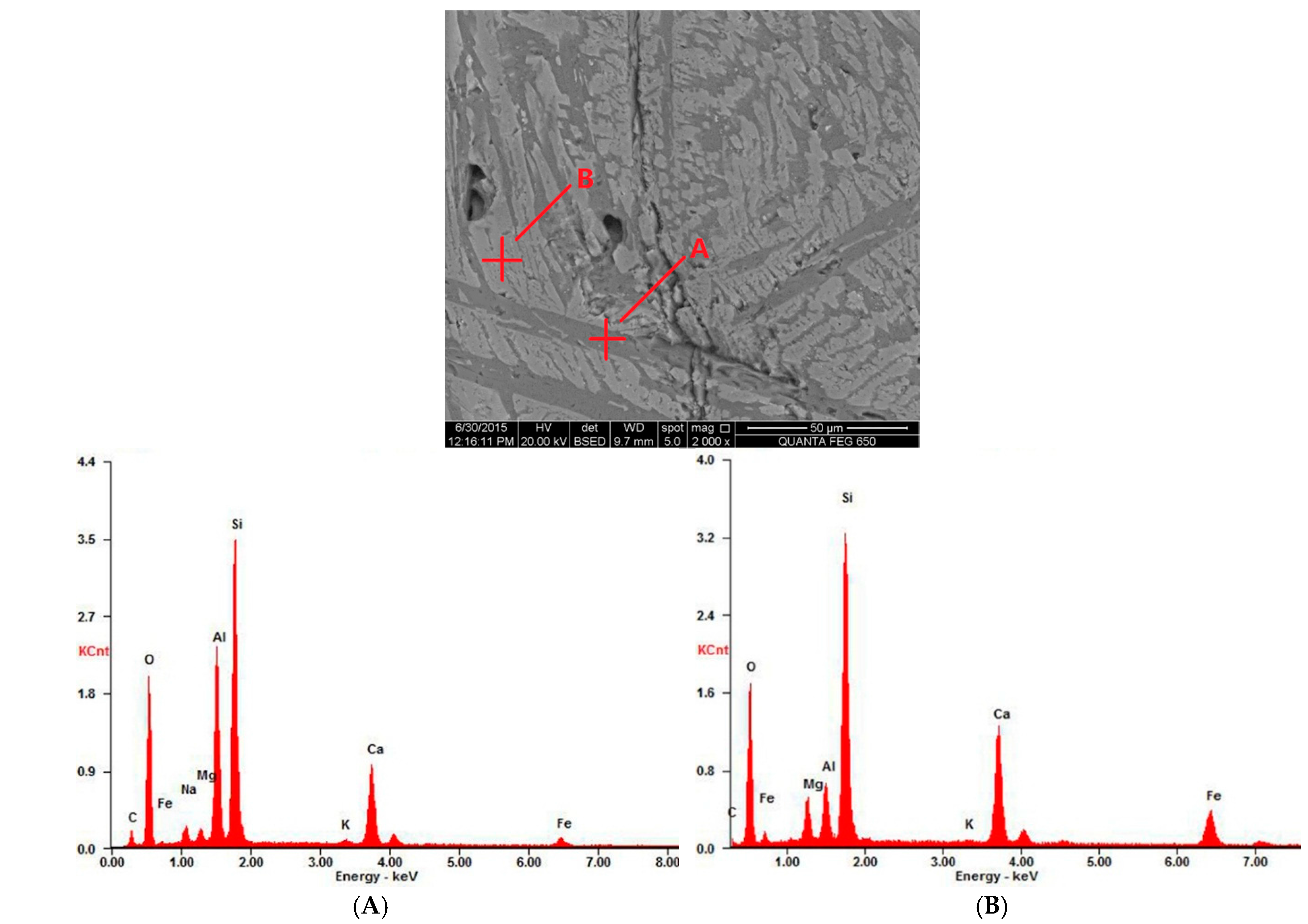
As shown in the SEM image in Figure 13, as a whole, 80%-O2 slag is mainly composed of two type of materials, phase “A” and phase “B.” From the Energy-Dispersive Spectrometer (EDS) quantitative analysis, as listed in Table 7, it is inferred that phase “A” contains anorthite crystals and phase “B” is the solid solution of gehlenite and pyroxene. The previous XRD analysis showed that in the 80%-O2 slag, the anorthite content is reduced, while gehlenite is formed in great quantities. Therefore, it can be concluded that anorthite forms in great quantities at 1200 °C and tends to melt as the temperature increases, so its crystal content gradually decreases until it finally disappears at 1400 °C. It is also reported that gehlenite is formed between 1200 and 1400 °C and begins to decrease above 1400 °C [37]. Thus, it is assumed that anorthite may provide a calcium source for the formation of gehlenite, which also accounts for the reduction of anorthite in the 80%-O2 slag.
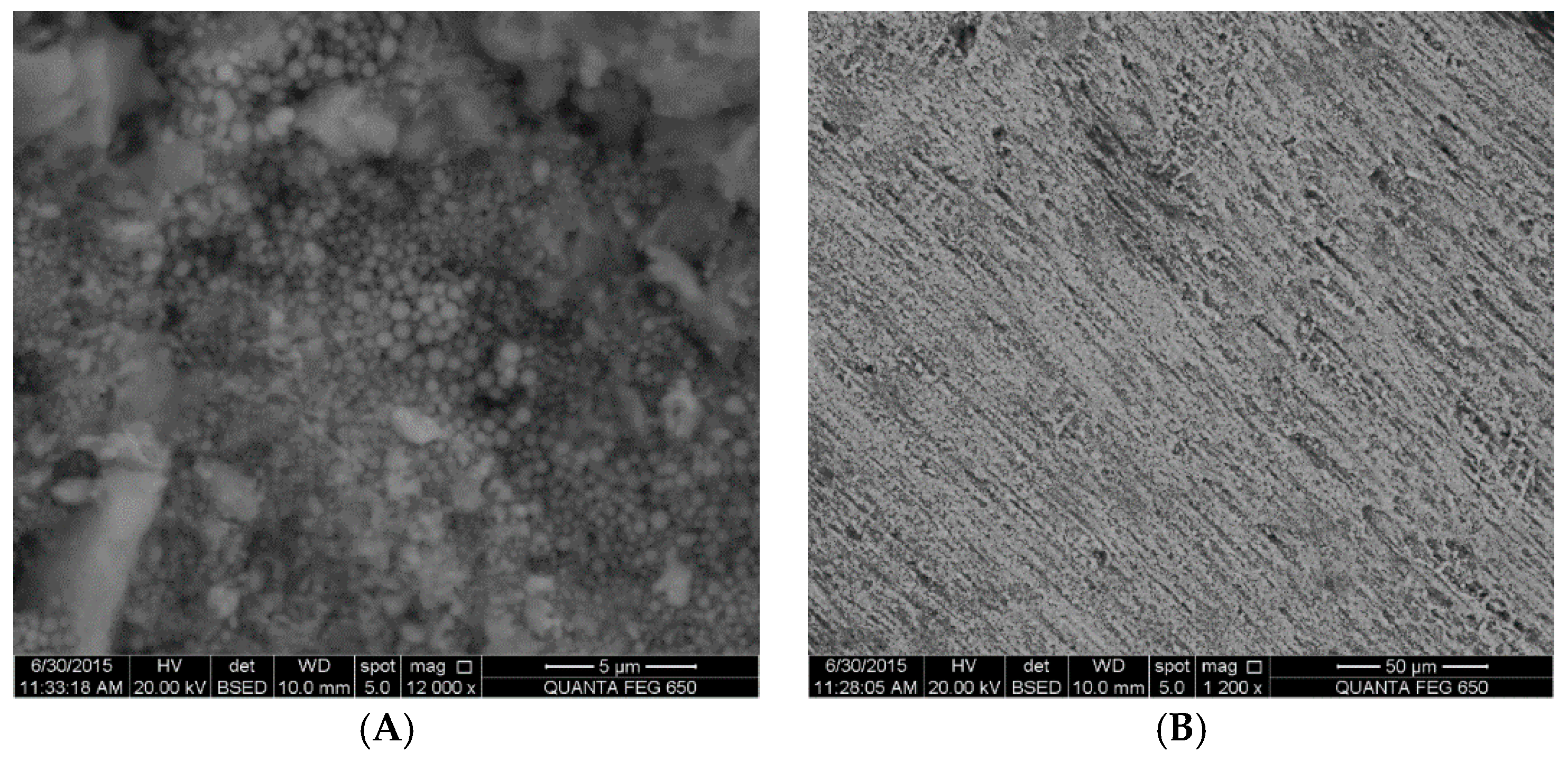
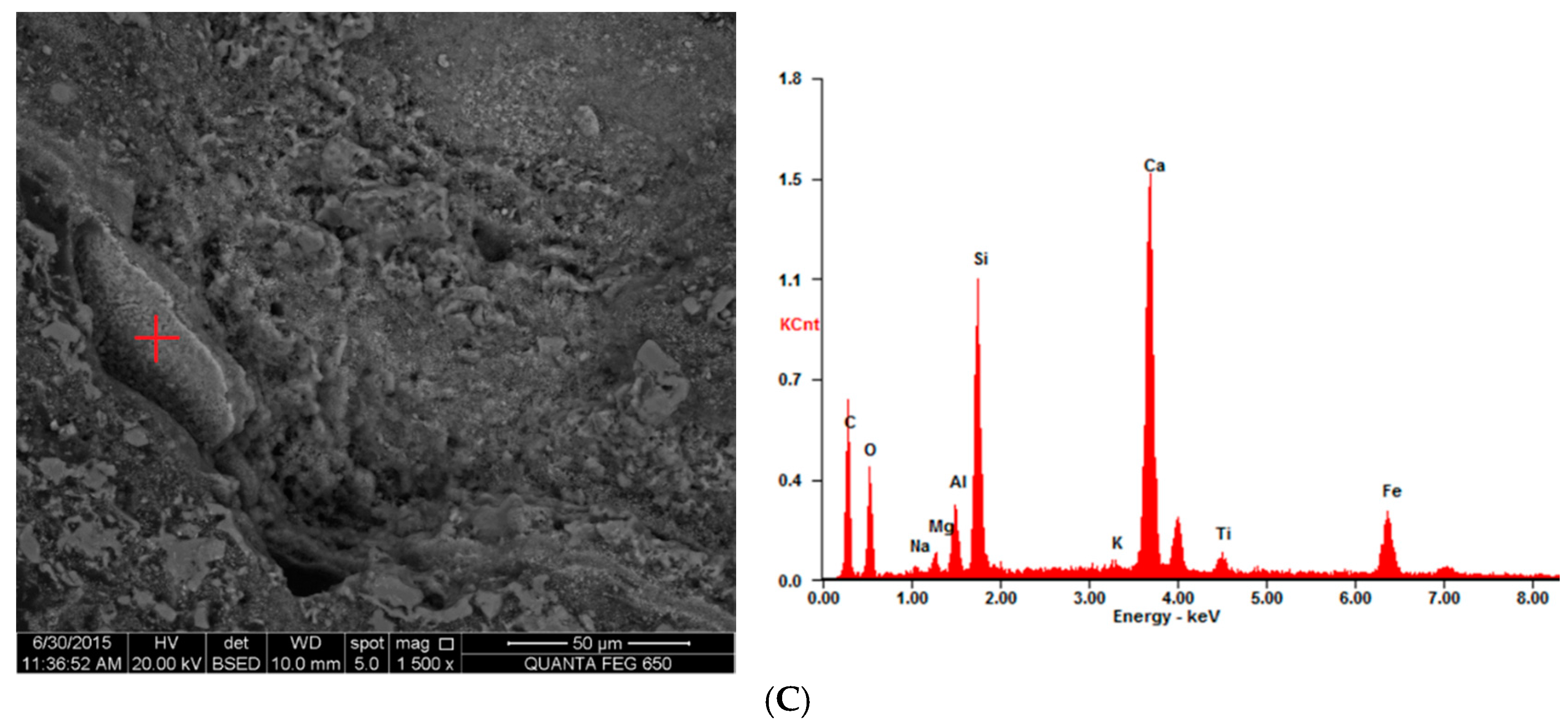
Based on the result of SEM-EDS analysis in Figure 14, sekaninaite is proven to exist in 40%-O2 slag. Moreover, iron oxide is also found in the form of Fe3O4, as concluded from the EDS quantitative results (Table 8). However, the iron-bearing mineral in 60%-O2 slag and 80%-O2 slag is mainly pyroxene on the basis of the SEM-EDS results, which is in agreement with the previous XRD quantitative analysis result. For the UCG residue, the existence of sekaninaite (Fe2Al4Si5O18) has been observed and proven to be the product of the reaction between SiO2 and hercynite (FeAl2O4) at high temperatures [20]. It has been reported that under oxygen-enriched gasification conditions, the iron-bearing mineral tends to react with aluminosilicate to form pyroxene [38]. Therefore, the reaction mechanism of iron-bearing minerals at high temperatures could be concluded to be iron mineral oxidizing to form magnetite (Fe3O4) and then converting to Fe2+ in hercynite during the gasification process (in a reductive atmosphere). Hercynite reacts with SiO2 to form sekaninaite, and then sekaninaite is further oxidized to produce pyroxene with the increase in oxygen concentration.

4. Conclusions

(1) The typical minerals in the 40%-O2 UCG slag include anorthite, mullite, sekaninaite, and approximately 49% amorphous substances. The mineral compositions of the 60%-O2 slag and 80%-O2 UCG slag are similar, and the dominant minerals involve anorthite, pyroxene, and gehlenite, while the amorphous substance almost disappears.
(2) In micro-appearance, the whole micro-morphology of the 40%-O2 slag is comparatively complicated, with unburned carbon in the form of plant cells and a large amount of porous and melting material observed. In contrast, the 60%-O2 slag seems to be homogeneous and is shown to have a wheat head formation. The homogeneous phenomenon is even more obvious in the 80%-O2 slag, with mineral crystals regularly arranged in lamellar stacks. It is inferred that the increased oxygen concentration during UCG is beneficial to the reformation of the mineral crystals and that the crystal structure of the minerals tends to be more orderly when the oxygen content increases from 40% to 80%.
(3) Mullite may react with the calcium oxide contained in slag to generate anorthite when the oxygen concentration is higher than 40%, which contributes to the disappearance of mullite and the remarkable increase of anorthite in the 60%-O2 slag. Anorthite may serve as a calcium source for the formation of gehlenite, which also accounts for the reduction of anorthite in the 80%-O2 slag.
(4) Sekaninaite is proven to exist in the low-oxygen-concentration slag; however, the iron-bearing mineral in higher-oxygen-concentration slag is mainly pyroxene. The reaction mechanism of iron-bearing minerals at high temperatures could be assumed to be iron mineral oxidizing to magnetite (Fe3O4) and then converting to Fe2+ of hercynite in a reducing atmosphere. The hercynite then reacts with SiO2 to form sekaninaite. Finally, with the increase in the oxygen concentration, sekaninaite is further oxidized to produce pyroxene.

Acknowledgments

The authors are grateful for the financial support provided by the National Basic Research Program of China (973 Program) (NO. 2014CB238905), the Natural Science Foundation of China (NO. 51476185), and the Fundamental Research Funds for the Central Universities (No. 2009QH13). The authors wish to thank Shifeng Dai for his great supports to X-Ray diffraction (XRD) and scanning electron microscope (SEM) analysis.

Author Contributions

Shuqin Liu conceived, designed, and performed the experiments and contributed reagents; Chuan Qi and Yunpeng Deng performed the experiments, performed the X-Ray diffraction (XRD) determination and thermodynamic simulation, observed the slag using SEM-EDS, and analyzed the data; Shangjun Zhang analyzed the data. All authors participated in writing the manuscript.

Conflicts of Interest

The authors declare no conflict of interest.

References

  1. Li, W.; Bai, J. Mineral composition and characterization of coals and coal ashes. In Chemistry of Ash from Coal; Science Press: Beijing, China, 2013; pp. 1–7. (In Chinese) [Google Scholar]
  2. Srinivasachar, S.; Helble, J.J.; Boni, A.A. An experimental study of the inertial deposition of ash under coal combustion conditions. In Twenty-Third Symposium (International) on Combustion; The Combustion Institute: Pittsburgh, PA, USA, 1991; Volume 23, pp. 1305–1312. [Google Scholar]
  3. Brooker, D. Chemistry of deposit formation in a coal gasification syngas cooler. Fuel 1993, 72, 665–670. [Google Scholar] [CrossRef]
  4. Marinov, V.; Marinov, S.P.; Lazarov, L.; Stefanova, M. Ash agglomeration during fluidized bed gasification of high sulphur content lignites. Fuel Process. Technol. 1992, 31, 181–191. [Google Scholar] [CrossRef]
  5. McLennan, A.R.; Bryant, G.W.; Bailey, C.W.; Stanmore, B.R.; Wall, T.F. An experimental comparison of the ash formed from coals containing pyrite and siderite mineral in oxidizing and reducing conditions. Energy Fuels 2000, 14, 308–315. [Google Scholar] [CrossRef]
  6. Raask, E. Mineral Impurities in Coal Combustion: Behavior, Problems, and Remedial Measures; Hemisphere Publishing Corporation: Washington, DC, USA, 1985; pp. 231–239. [Google Scholar]
  7. Wagner, N.J.; Coertzen, M.; Matjie, R.H.; van Dyk, J.C. Coal gasification. In Applied Coal Petrology; Suárez-Ruiz, I., Crelling, J.C., Eds.; Elsevier Publications: Amsterdam, The Netherlands, 2008; pp. 119–144. [Google Scholar]
  8. Koyama, S.; Morimoto, T.; Ueda, A.; Matsuoka, H. A microscopic study of ash depositsin a two-stage entrained-bed coal gasifier. Fuel 1996, 75, 459–465. [Google Scholar] [CrossRef]
  9. Slade, R.C.T.; Davies, T.W. Evolution of structural changes during flash calcination of kaolinite. A 29Si and 27Al nuclear magnetic resonance spectroscopy study. J. Mater. Chem. 1991, 1, 361–364. [Google Scholar] [CrossRef]
  10. Srinivasachar, S.; Helble, J.J.; Boni, A.A. Mineral behavior during coal combustion 1. Pyrite transformations. Prog. Energy Combust. Sci. 1990, 16, 281–292. [Google Scholar] [CrossRef]
  11. Ranjan, S.; Sridhar, S.; Fruehan, R.J. Reaction of FeS with simulated slag and atmosphere. Energy Fuels 2010, 24, 5002–5007. [Google Scholar] [CrossRef]
  12. Hu, G.; Dam-Johansen, K.; Wedel, S.; Hansen, J.P. Decomposition and oxidation of pyrite. Prog. Energy Combust. Sci. 2006, 32, 295–314. [Google Scholar] [CrossRef]
  13. Miller, S.F.; Schobert, H.H. Effect of the occurrence and composition of silicate and aluminosilicate compounds on ash formation in pilot-scale combustion of pulverized coal and coal-water slurry fuels. Energy Fuels 1994, 8, 1197–1207. [Google Scholar] [CrossRef]
  14. Raask, E. Creation, capture and coalescence of mineral species in coal flames. J. Inst. Energy 1984, 57, 231–239. [Google Scholar]
  15. Helble, J.J.; Srinivasachar, S.; Boni, A.A. Factors influencing the transformation of minerals during pulverized coal combustion. Prog. Energy Combust. Sci. 1990, 16, 267–279. [Google Scholar] [CrossRef]
  16. Brink, H.M.; Eenkhoorn, S.; Weeda, M. The behaviour of coal mineral carbonates in a simulated coal flame. Fuel Process. Technol. 1996, 47, 233–243. [Google Scholar] [CrossRef]
  17. Yan, L.; Gupta, R.P.; Wall, T.F. The implication of mineral coalescence behaviour on ash formation and ash deposition during pulverised coal combustion. Fuel 2001, 80, 1333–1340. [Google Scholar] [CrossRef]
  18. Yan, L.; Gupta, R.P.; Wall, T.F. Ash formation from excluded minerals including consideration of mineral-mineral associations. Energy Fuels 2007, 21, 461–467. [Google Scholar]
  19. Jing, N.J.; Wang, Q.H.; Cheng, L.M.; Luo, Z.Y.; Cen, K.F.; Zhang, D.K. Effect of temperature and pressure on the mineralogical and fusion characteristics of Jincheng coal ash in simulated combustion and gasification environments. Fuel 2013, 104, 647–655. [Google Scholar] [CrossRef]
  20. McCarthy, G.J.; Stevenso, R.J.; Oliver, R.L. Mineralogical characterization of the residues from the Tono I UCG experiment. In Proceedings of the Fourteenth Annual Underground Coal Gasification Symposium, Chicago, IL, USA, 15–18 August 1988; pp. 41–50.
  21. Chen, Z.W.; Liu, J.S.; Pan, Z.J.; Connell, L.D.; Elsworth, D. Influence of the effective stress coefficient and sorption-induced strain on the evolution of coal permeability: Model development and analysis. Int. J. Greenh. Gas Control 2012, 8, 101–110. [Google Scholar] [CrossRef]
  22. Standardization Administration of the People’s Republic of China. Proximate Analysis of Coal 2008; Chinese Standard GB/T 212-2008; Standardization Administration of the People’s Republic of China: Beijing, China. (In Chinese)
  23. Standardization Administration of the People’s Republic of China. Determination of Carbon and Hydrogen in Coal 2008; Chinese Standard GB/T 476-2008; Standardization Administration of the People’s Republic of China: Beijing, China. (In Chinese)
  24. Standardization Administration of the People’s Republic of China. Determination of Nitrogen in Coal 2008; Chinese Standard GB/T 214-2007; Standardization Administration of the People’s Republic of China: Beijing, China. (In Chinese)
  25. Standardization Administration of the People’s Republic of China. Determination of Total Sulfur in Coal 2008; Chinese Standard GB/T 212-2008; Standardization Administration of the People’s Republic of China: Beijing, China. (In Chinese)
  26. Standardization Administration of the People’s Republic of China. Classification for Quality of Coal. Part 2: Sulfur, 2010; Chinese Standard GB/T 15224, 2–2010; Standardization Administration of the People’s Republic of China: Beijing, China. (In Chinese)
  27. Standardization Administration of the People’s Republic of China. Test Method for Analysis of Coal Ash 2008; Chinese Standard GB/T 1574-2007; Standardization Administration of the People’s Republic of China: Beijing, China. (In Chinese)
  28. Standardization Administration of the People’s Republic of China. Determination of Fusibility of Coal Ash 2008; Chinese Standard GB/T 219-2008; Standardization Administration of the People’s Republic of China: Beijing, China. (In Chinese)
  29. Ward, C.R.; Spears, D.A.; Booth, C.A.; Staton, I.; Gurba, L.W. Mineral matter and trace elements in coals of the Gunnedah Basin, New South Wales, Australia. Int. J. Coal Geol. 1999, 40, 281–308. [Google Scholar] [CrossRef]
  30. Dai, S.; Wang, P.; Ward, C.R.; Tang, Y.; Song, X.; Jiang, J.; Hower, J.C.; Li, T.; Seredin, V.V.; Wagner, N.J.; et al. Elemental and mineralogical anomalies in the coal-hosted Ge ore deposit of Lincang, Yunnan, southwestern China: Key role of N2–CO2-mixed hydrothermal solutions. Int. J. Coal Geol. 2015, 152, 19–46. [Google Scholar] [CrossRef]
  31. Dai, S.; Liu, J.; Ward, C.R.; Hower, J.C.; French, D.; Jia, S.; Hood, M.M.; Garrison, T.M. Mineralogical and geochemical compositions of Late Permian coals and host rocks from the Guxu Coalfield, Sichuan Province, China, with emphasis on enrichment of rare metals. Int. J. Coal Geol. 2015. [Google Scholar] [CrossRef]
  32. Van Dyk, J.C.; Melzer, S.; Sobiecki, A. Mineral matter transformation during Sasol-Lurgi fixed bed dry bottom gasification-utilization of HT-XRD and FactSage modelling. Miner. Eng. 2006, 19, 1126–1135. [Google Scholar] [CrossRef]
  33. Bale, C.W.; Chartrand, P.; Degterov, S.A.; Eriksson, G.; Hack, K.; Manfoud, R.B.; Melancon, J.; Pelton, A.D.; Peterson, S. FactSage thermochemical software and databases. Calphad 2002, 26, 189–228. [Google Scholar] [CrossRef]
  34. Matjie, R.H.; Li, Z.S.; Ward, C.R.; French, D. Chemical composition of glass and crystalline phases in coarse coal gasification ash. Fuel 2008, 87, 857–869. [Google Scholar] [CrossRef]
  35. Wu, X.J.; Zhang, Z.X.; Zhou, T.; Chen, Y.S.; Chen, G.Y.; Lu, C.; Huang, F.B. Ash fusion characteristics and mineral evolvement of blended ash under gasification condition. J. Combust. Sci. Technol. 2010, 16, 511–512. [Google Scholar]
  36. Grim, R.E. Clay Mineralogy, 2nd ed.; McGraw-Hill Book Company: New York, NY, USA, 1968; p. 173. [Google Scholar]
  37. Li, W.; Bai, J. Mineral transformation during thermal conversion of coals. In Chemistry of Ash from Coal; Science Press: Beijing, China, 2013; p. 52, ( In Chinese). [Google Scholar]
  38. Huang, Z.Y.; Li, Y.; Zhao, J.; Zhou, Z.J.; Zhou, J.H.; Cen, K.F. Ash fusion regulation mechanism of coal with melting point and different ash compositions. J. Fuel Chem. Technol. 2012, 40, 1038–1043. [Google Scholar]
Figure 1. Sketch of the underground coal gasification (UCG) process.
Minerals 06 00027 g001
Figure 2. A schematic diagram of an Underground Coal Gasification (UCG) simulation facility.
Minerals 06 00027 g002
Figure 3. Schematic diagram of coal bed layout.
Minerals 06 00027 g003
Figure 4. UCG cavity and UCG slag in different atmospheres. (A) UCG cavity; (B) 40%-O2 slag; (C) 60%-O2 slag; (D) 80%-O2 slag.
Minerals 06 00027 g004
Figure 5. Temperature profile distribution during UCG simulation test (40%-O2).
Minerals 06 00027 g005
Figure 6. Temperature profile distribution during UCG simulation test (60%-O2).
Minerals 06 00027 g006
Figure 7. Temperature profile distribution during UCG simulation test (80%-O2).
Minerals 06 00027 g007
Figure 8. XRD patterns of coal and UCG slag. Q-Quartz; Py-Pyroxene; A-Anorthite; S-Sekaninaite; G-Gehlenite; P-Pyrite; C-Chlorite; K-Kaolinite; Mu-Mullite.
Minerals 06 00027 g008
Figure 9. Melting material and unburned carbon in 40%-O2 slag, SEM back scattering images. (A) Porous and melting materials; (B) Unburned carbon.
Minerals 06 00027 g009
Figure 10. Thermodynamic simulation of mineral transformation in 40%-O2 gasification condition.
Minerals 06 00027 g010
Figure 11. Amorphous glass beads and wheat head formation crystals in 60%-O2 slag, SEM back-scattering images. (A) Amorphous glass beads; (B) Wheat head formation crystals.
Minerals 06 00027 g011
Figure 12. Rod-like stacks crystals and lamellar stacks crystals in 80%-O2 slag, SEM back scattering images. (A) Rod-like stacks crystals; (B) Lamellar stacks crystals.
Minerals 06 00027 g012
Figure 13. Scanning electron microscope and energy-dispersive spectrometer (SEM-EDS) analysis of minerals in 80%-O2 slag. (A) Anorthite crystals; (B) Solid solution of gehlenite and pyroxene.
Minerals 06 00027 g013
Figure 14. SEM-EDS analysis of Fe-bearing minerals in UCG slag. (A) Sekaninaite in 40%-O2 slag, EDS analysis; (B) Melting iron oxide in 40%-O2 slag, EDS analysis; (C) Pyroxene crystals in 60%-O2 slag, EDS analysis.
Minerals 06 00027 g014aMinerals 06 00027 g014b
Table 1. Proximate and ultimate analysis of the test coal (%).
Proximate Analysis/%Ultimate Analysis/%
MadAadVadFCadCadHadOadNadSt,ad
11.5029.1028.4730.9343.703.1111.590.570.65
M, moisture; A, ash; V, volatile matter; FC, fixed carbon; C, carbon; H, hydrogen; O, oxygen; N, nitrogen; St, total sulfur; ad, air dried basis.
Table 2. Ash composition of lignite (wt %).
OxideSiO2Al2O3Fe2O3TiO2CaOMgOK2ONa2OMnO2SO3P2O5
Content59.0418.025.830.935.802.712.741.261.262.500.20
Table 3. Coal ash fusibility (°C).
Deformation Temperature (DT)Softening Temperature (ST)Hemispherical Temperature (HT)Flow Temperature (FT)
1160120012301270
Table 4. Input into calculations.
Element40%-O2 Gasification (g)60%-O2 Gasification (g)80%-O2 Gasification (g)
C184.65247.98308.67
H13.1417.6521.97
O397.15536.51628.44
N459.39277.83123.59
S2.753.694.59
Si33.8945.5156.65
Al11.7515.7819.64
Fe5.036.758.41
Ti0.680.911.13
Ca5.116.878.55
Mg1.992.673.32
K2.793.754.66
Na1.141.531.91
Mn0.040.060.07
P0.130.170.21
Table 5. Gas composition under oxygen-enriched gasification conditions (V%).
Oxygen (%)H2COCH4CO2N2O2Heat Value MJ/N·m3
4021.0615.041.5025.8535.670.724.70
6030.1124.861.2526.7516.810.136.82
8031.3327.291.0331.698.360.217.18
Table 6. Mineral composition of UCG slag by XRD analysis and Siroquant.
Mineral CompositionRaw Coal40%-O2 Slag60%-O2 Slag80%-O2 Slag
Quartz29.61.59.31.8
Illite43.3
Kaolinite21.5
Chlorite1.4
Pyrite4
Anorthite13.759.745.4
Pyroxene25.726.3
Gehlenite1.326.4
Sekaninaite11.5
Mullite22.3
Amorphous49.03.6
Note: “—”, less than 1%.
Table 7. Energy-dispersive spectrometer (EDS) quantitative results of anorthite crystals and gehlenite and pyroxene solid solution in 80%-O2 slag (wt %).
ElementCONaMgAlSiKCaFe
A6.935.71.71.013.726.60.610.83.0
B7.232.73.44.424.50.414.812.6
A: Anorthite crystals; B: Solid solution of gehlenite and pyroxene. Note: “—”, undetectable.
Table 8. EDS quantitative results of iron-containing minerals in UCG slag.
ElementCONaMgAlSiKCaFeTi
A10.137.90.61.911.828.32.71.85.0
B6.024.30.21.63.30.21.463.3
C23.918.40. 51.02.911.50.726.82.112.2
A, Sekaninaite in 40%-O2 slag; B, Melting iron oxide in 40%-O2 slag; C, Pyroxene crystals in 60%-O2 slag. Note: “—”, undetectable.

